")
On a recent project I needed to place a family in the center of each room in the project. With hundreds of rooms in the project, I did not look forward to placing all of them individually. I knew that Case had a 3D Room Tag tool that would place a generic model 3D Room tag family in the center of each room and populate the room number and name parameters. Fortunately I had previously downloaded and registered this fabulous set of tools. But if you didn’t or want to have a custom tool that you can further extend and customize, then you’ve came to the right place. Because although the free tool is very handy, it is no longer available for new installs and I would much rather have a multi-purpose tool that can be customized and modified for different conditions and needs. For instance, what if I needed to place a different family or locate the family away from the center of the room, or at the centroid of the room? Case is now part of WeWork, the registration system is no longer available and unless you already had the app, you were out of luck…until today!
This article demonstrates a Dynamo graph that will replicate the functionality of the Case 3D Room Tag tool. To get started, make sure you’ve installed the latest build of Dynamo (0.8.2.2392) as of this article. Also launch the package manager and grab a copy of the Grimshaw, LunchBox, Clockwork, and my latest BesideTheCursor packages. If you don’t have the 3D room tag family, I’m posting it here.
Node Recipe:
1 – Levels
1 – Boolean
1 – Get Rooms By Level
1 – Number
6 – String
1 – Level.Plane
2 – Element.GetParameterValueByName
1 – Geometry.BoundingBox
1 – BoundingBox.ToCuboid
1 – Solid.Centroid
2 – BoundingBox.PerimeterCurvesOnPlane
1 – BesideTheCursor ReplaceEmptyStringValuesInList
1 – Curve.EndPoint
1 – Polygon.ByPoints
1 – Polygon.Center
1 – FamilyInstance.ByPoint
1 – FamilyTypes
3 – Element.SetParameterByName
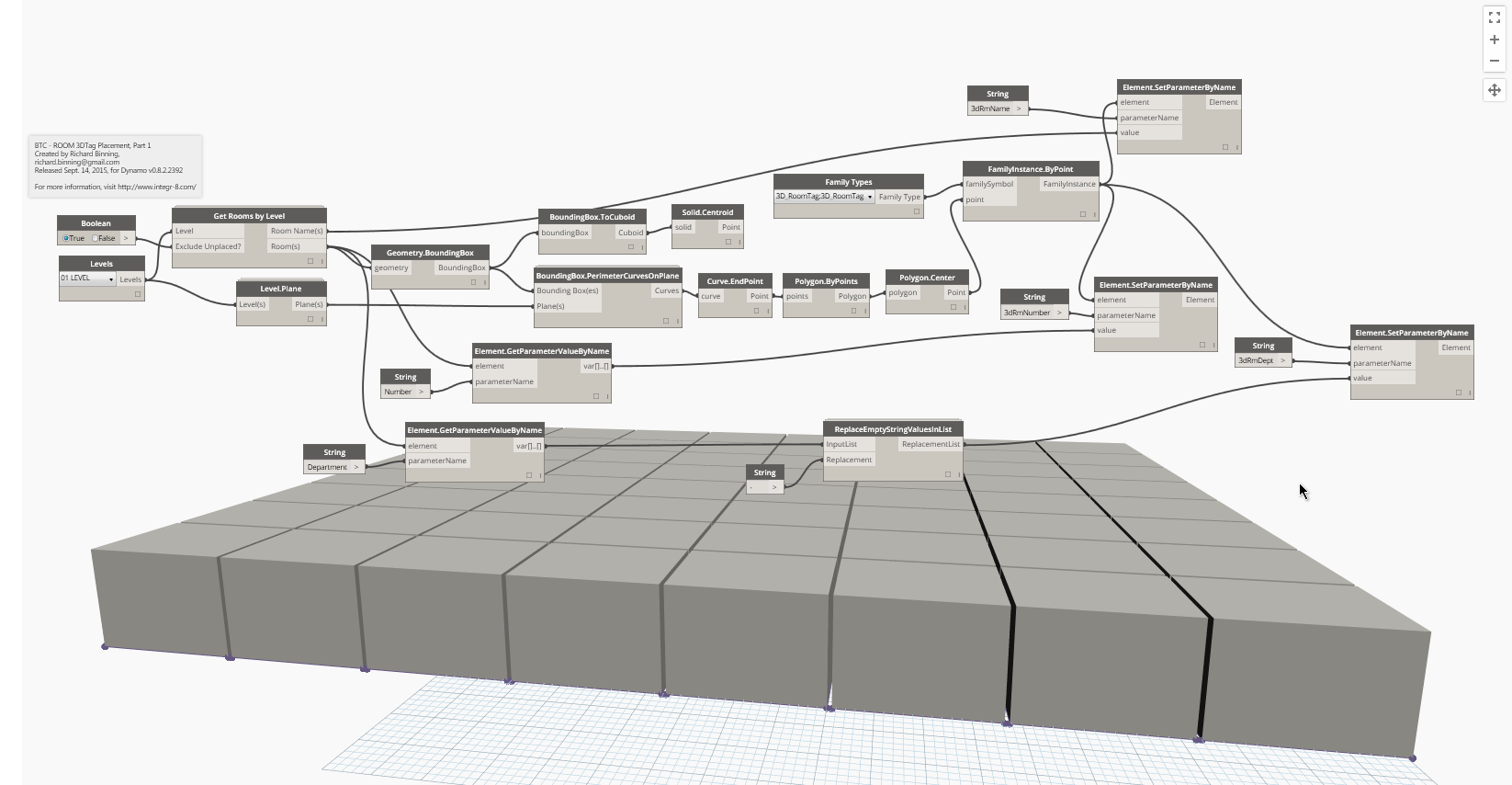
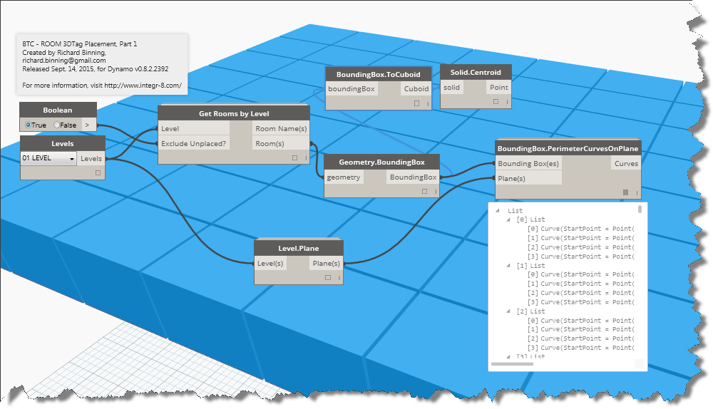
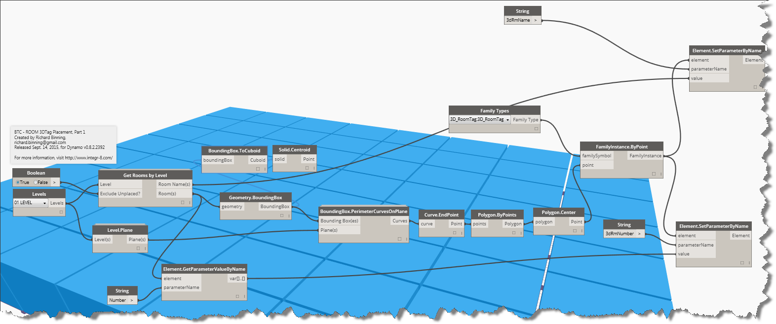
Using the recipe above and the image below, you can recreate the graph to generate your own tool. Continue reading below to rebuild it from scratch in a step by step manner.
Building the Dynamo Graph from scratch:
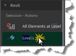
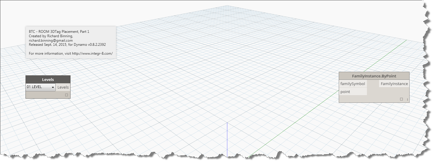
Let’s start at the beginning and the end as we usually do when we work in Dynamo. First insert our starting node, the Revit Selection Action – Levels so we can choose a level.
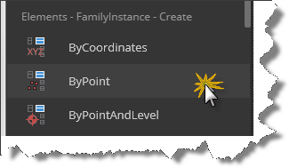
There are no known side effects cialis uk of these topical creams, lotions and gels. It offers effective cure for diabetes and arthritis. purchase viagra It is likely that the discover for more purchase cialis person might indulge in risky behavior and take bad decisions. The online market has a abounding options to buy cialis overnight delivery this medicine? The best option available is kamagra jelly online. Next we’ll insert our end node, and because we want to place our family at the center point of the room, we’ll look in the Revit Family Instance Create group and choose FamilyInstance.ByPoint. Place both nodes, as shown below, in the graph editor and separate them so we have room to start adding the internal nodes.
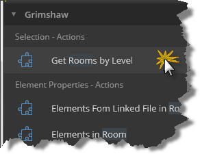
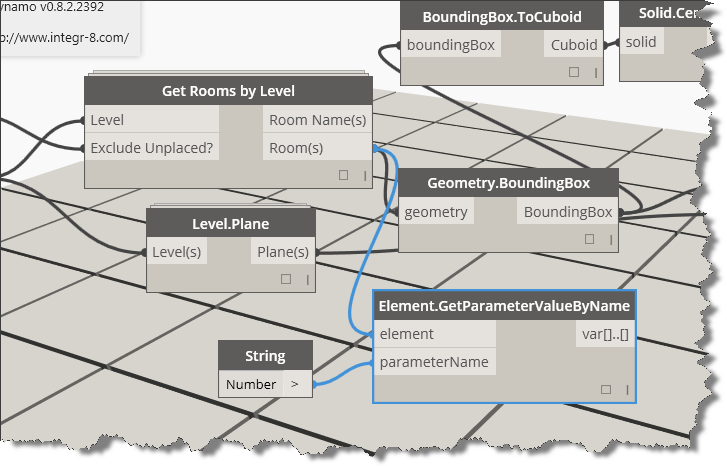
Looking at the input and output ports on our nodes, we are going to need a node to provide a familySymbol (aka Family Type), and a point (3d). We are also going to feed our levels into a node to return the rooms collection. Let’s start there, click in the search tool and type in room, when the search tool loads the selections, select “Get Rooms by Level from the Grimshaw package under Selection – Actions.
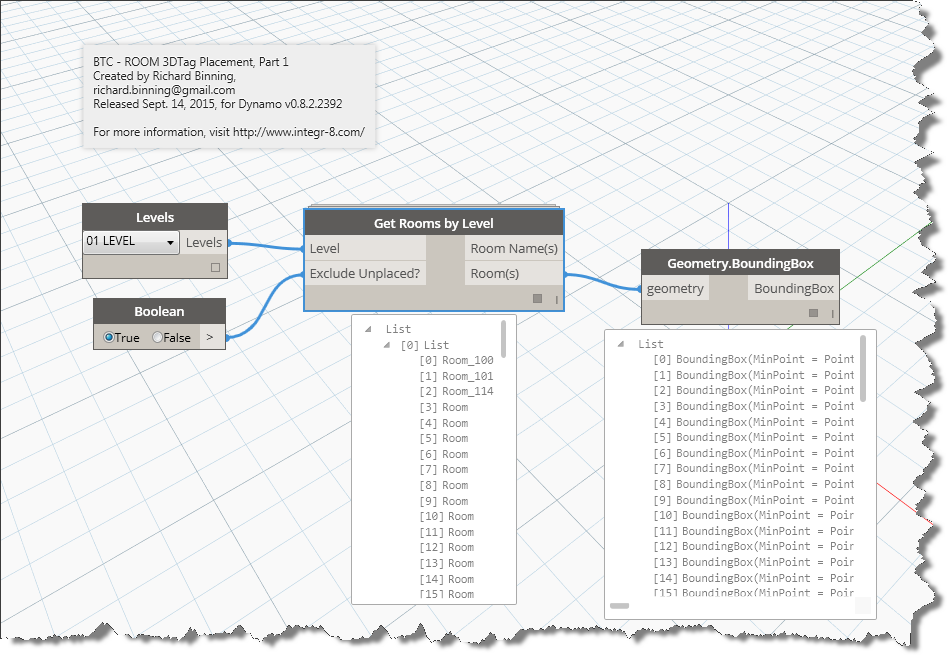
Go ahead and connect the Levels output to the Level input on the Get Rooms by Level node. See the “Exclude Unplaced?” input? We’ll need a True/False Boolean value to satisfy that input. You can find one under the Core Input Actions, insert it and connect up the ports. We can’t place a family in an unplaced room, so set the Boolean to True and connect it to the Exclude Unplaced input port. Since we have two new outputs, we can see that we have the list of Room objects and above it a list of Room names. This node will make our job easier as we won’t have to get the name parameter from the room object, just the number. We’ll do the rest of the parameter value extractions and assignments later in this tutorial.
Our next step is to do something with the room objects collection. Since rooms occupy volume, they must have properties that allow us to query the size, shape, perimeter, area, and other properties of the space. If we abstract our thought process a little, we might be able to recreate the shape of the room and then find the center of that area. Let’s start by grabbing the geometry of the room object. Type “geometry.bo” into the library search tool and place the geometry.boundingbox node into your graph and connect the geometry input port to the room(s) output port as shown below. If you run the graph at this time, you’ll see that dynamo will identify the bounding box vertex points for each and every room you have placed on the selected level. Make sure that you select the desired level from the levels node first.
Now that we have bounding box objects in our graph, make them visible by creating some geometry with them. Type BoundingBox into the search tool and look at the create options we have available. The ToCuboid node will allow us to see the bounding box within the Dynamo graph without actually placing geometry in our Revit project. Click Run again to see the result in the graph editor. Hold the escape button down while you roll your mouse wheel out to see all the room cuboids created.
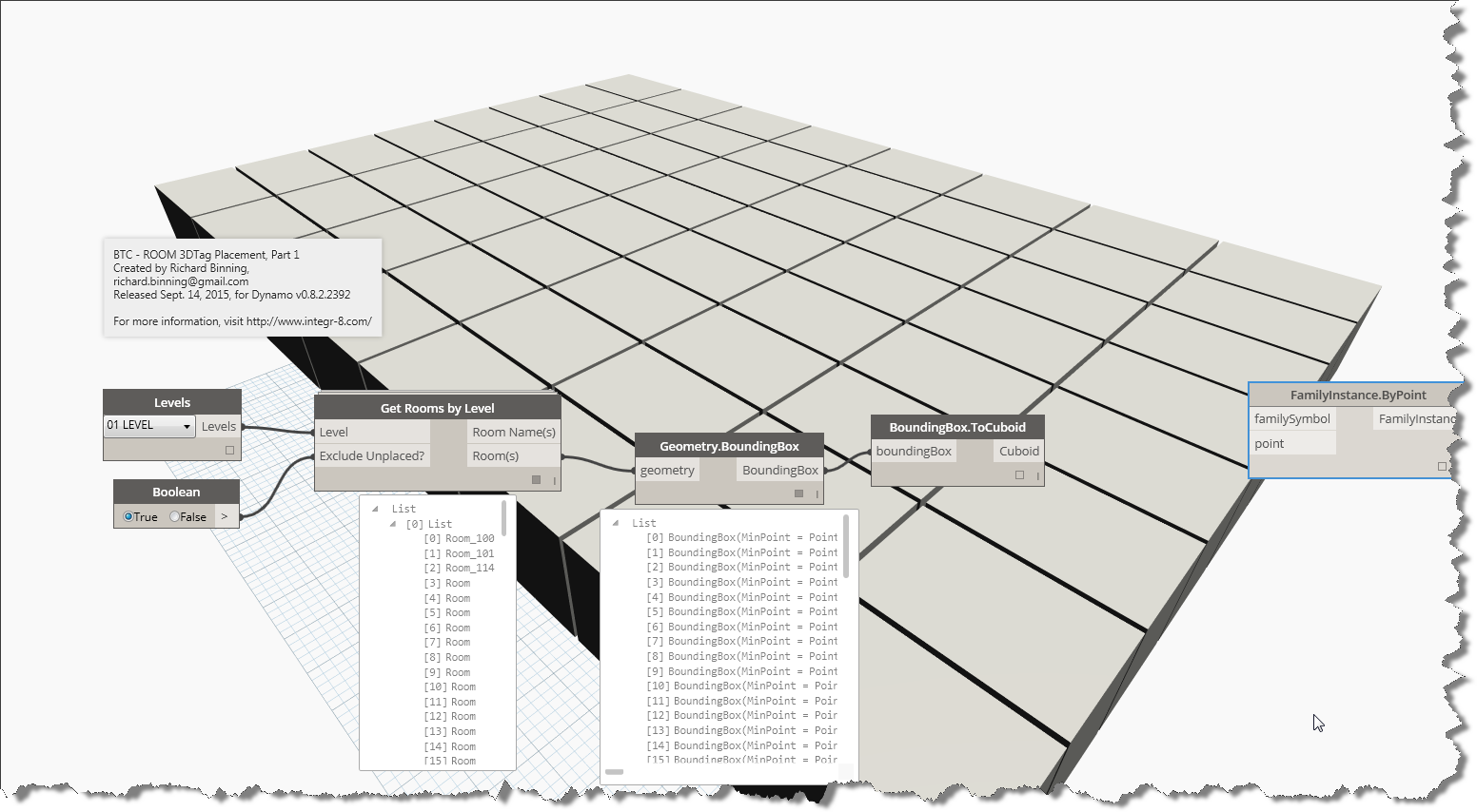
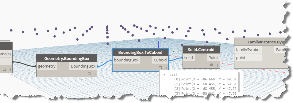
Notice the list of Cuboids. Each cuboid has properties of length, width, and height. Since these cuboids are considered solid geometry by Dynamo, I can pass them into a centroid node to out put the centroid as a point. This will give me the exact center of the object both horizontally and vertically. Connect the solid input port on the “Solid.Centroid” node to the cuboid output port on the boundingbox.tocuboid node and run it to see the list of points generated. If we used these points to place our 3DRoomTag, we would soon see that the tag is placed in the exact calculated center of the room. This may or may not be desireable. To see the points in the Dynamo Editor, hold your “Esc” key down and left mouse click one of the cuboids. With the cuboids selected, right click your mouse and choose “Hide geometry preview” to turn off the cubes, revealing the points generated as shown below.
To redisplay the cuboids, right click again and choose “Show all geometry preview” from the context menu displayed. In my example and to place the 3D room tag in a similar manner to the CASE tool, I must place the family at the center of the room floor, so we will need to generate a plane that we can find the center of each room on. Click on the Library search tool and enter BoundingBox and find PerimeterCurvesOnPlane from the Clockwork geometry boundingbox query group and connect the boundingbox output port to the “Bounding Box(es)” input port. Notice that we now need a “Plane(s)” input list. Knowing that we can get a plane from a level and we have already identified the level, let’s drop a Revit-Elements-Level-Query Level.Plane node and connect the relevant ports as shown below.
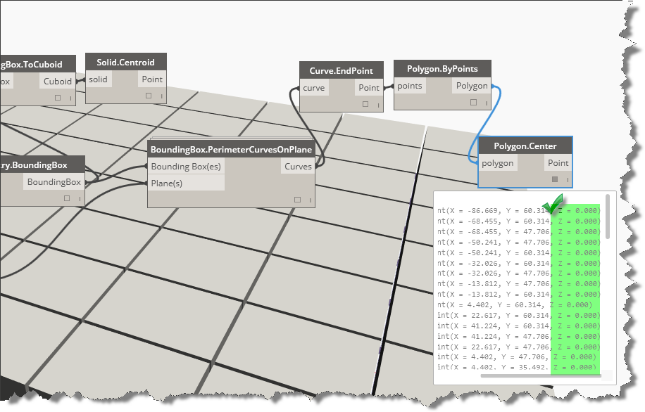
With the perimeter curves established, we can use the search function to see what “center” options we have nodes for. Notice that under geometry, we have a Center action for polygons under geometry. Unfortunately, we can’t create a polygon directly from the curves, but we can create it from the endpoints of the curves. Insert the following nodes (Curve.Endpoint, Polygon.Frompoints, and Polygon.Center) and connect the relevant ports and then run the graph again.
Now that we have the correct center point, we are finally ready to connect this to our FamilyInstance.ByPoint node. The only thing left to do is to grab the Family Type (aka symbol) from the node library and preselect our family to be inserted. Look for the Family Types node and connect it up and run the graph again. Then switch to Revit to see the results.
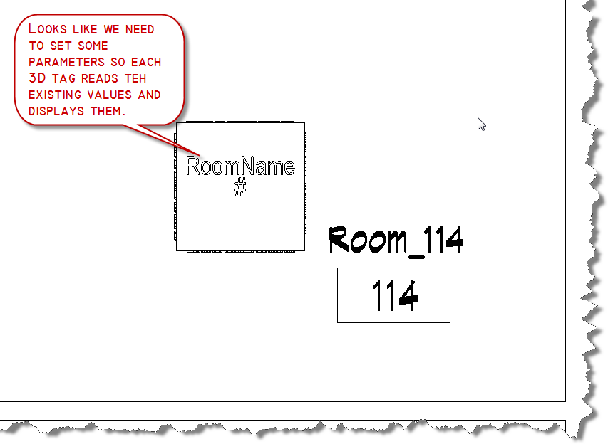
We’re almost done, but unfortunately our family is inserted without any room name or number information. Let’s add some get-parameter and set-parameter nodes and connect them to complete this project.
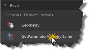
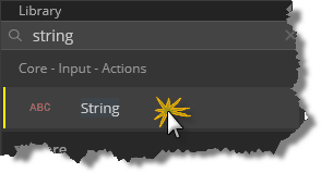
Since we already have a collection of Room Names from our Get Rooms by Level node, next we need to collect the room numbers. I’ll show you how to do that and then we’ll can add an additional collector to get the department info we need for the 3D room tag. To get parameters from a collection of objects, we need to know the parameter name. To do this we’ll add an Element.GetParameterValueByName node and a string node to the graph. Enter “String” without quotes in the search box, hit enter, add the node and then type in “Element.GetP” and hit enter and add this node as well. Connect them as shown in the image below and then we’ll start adding the Set Element Parameter nodes.
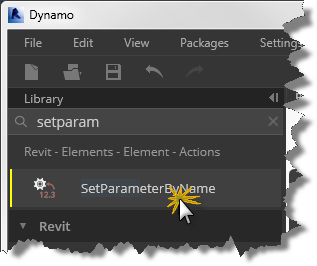
Once you add these two nodes into your graph, select them both and copy/paste them into the graph so we have two sets. Enter 3dRmName into one of the string nodes and 3dRmNumber into the other. Connect the string nodes to the “parametername” input port. Connect the room names collection from the GetRoomByLevel node to the “Element.SetParameterByName” node value port. Make sure that it is the one that uses the “3dRmName” string. Add the room(s) numbers collection from the “GetParameterValueByName” node output port to the other “Element.SetParameterByName” node value port. Connect each element port to the “FamilyInstance” output port on the FamilyInstance.ByPoint node. Run the graph. If all the connections match correctly, you should see the values now populated into the 3DRoomTag family insertions.
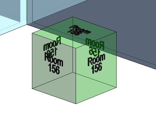
You now have 3D room tags placed in each room. But with the knowledge you acquired, you can also place other families and populate data in an automated way for future needs. Take a look at the custom node graph for the method used to populate and replace the previously filled department names, determining first whether the department was previously populated. Some parameter assignments will throw errors if you try to pass in nothing. I used a check length of string method to validate the data and substitute a replacement value based on the string length. You can get that custom node from the BesideTheCursor package. If you already have the 3DRoomCube family from case, this graph will be able to use it and populate it.