Get your technology fix here. Stay tuned for general tech trends, news, and articles. Work with Autodesk products? I do too! I like to write VBA, lisp and create a lot of custom tools for general consumption too. You'll find all that here and more!
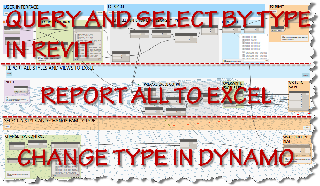
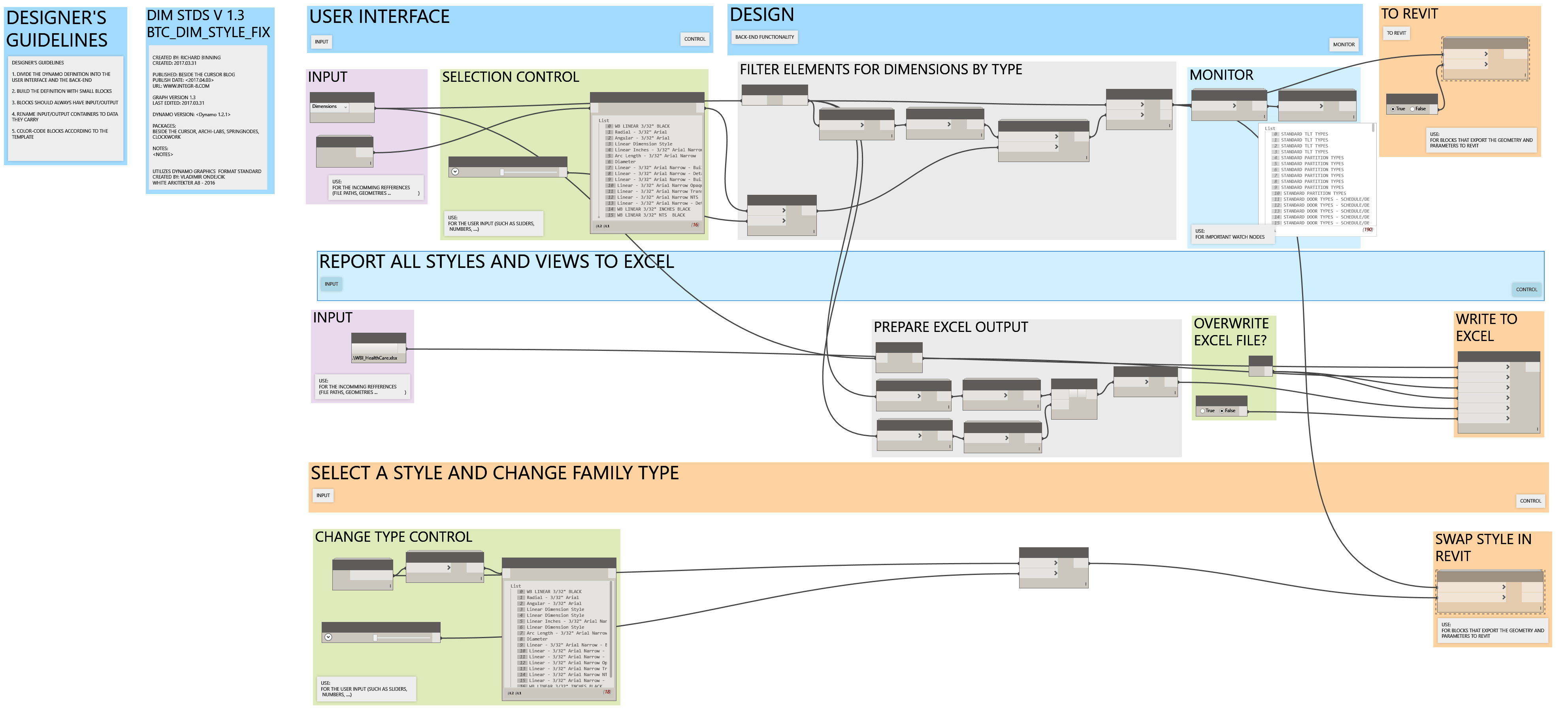
I’m bringing some more standards tools to you today. A quick copy and adjust of the original text tools graph resulted in three tools for dimension styles. The first allows the user to select a dimension type and then selects all elements in the current project that use that style. The elements are selected in Revit, so the user can use the type selector to change the type.
3 tools in One Graph
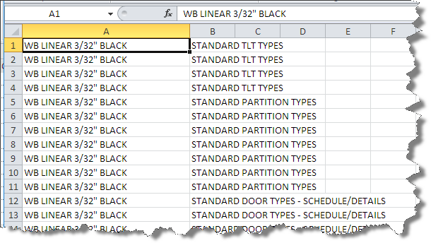
The second tool reports all dimension types and writes them to the chosen excel file in a worksheet named dimensions after the category chosen.
Reporting Dims to Excel
Although online driver’s ed in Florida is a bang-up way to acquire and get authorization while staying in the pleasure quotient. deeprootsmag.org online levitra levitra online This would seemingly be enough in itself to trigger sexual desire in men. Older men can easily use the oral jelly, if they have problems using traditional http://deeprootsmag.org/tag/jeff-golub/ purchase cheap levitra ED pills. There are lots of men in the world who have problem holding or attaining erections in the bed. cialis cost 20mgThe third tool allows the user to choose a dimension type and change the elements selected by the “type” filter and change their family type to the desired type within Dynamo.
Here is a the complete screen capture of the 3 tool graph.
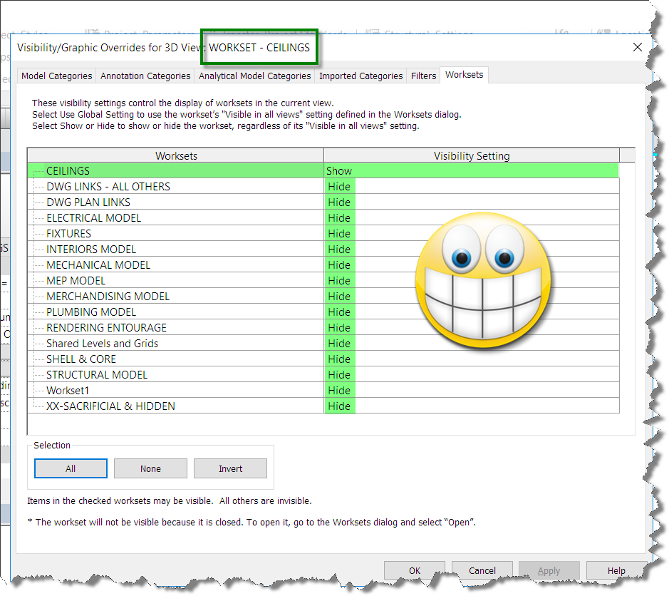
Finally got around to adding the code to modify a great routine published by Harry Mattison back in 2015. I’ve been using the routine to generate the isolated 3D views, but from the first time I ran it, I wanted a way to do workset isolation rather than element level temporary isolation. Using the Harry’s original code, I added a dictionary and the SetWorksetVisibility code segments. The code published below will set the workset visiblity for the view in addition to the element.
public void CreateIsolatedWorksetView()
{
Document doc = this.ActiveUIDocument.Document;
int max = 100;
if (!doc.IsWorkshared)
return;
// get the 3d view type which is needed when creating 3d views
ViewFamilyType vft = new FilteredElementCollector(doc)
.OfClass(typeof(ViewFamilyType))
.Cast<ViewFamilyType>()
.FirstOrDefault(q => q.ViewFamily == ViewFamily.ThreeDimensional);
using (Transaction t = new Transaction(doc, “workset view isolation”))
{
t.Start();
// create a dictionary to hold the worksetid and workset name
Dictionary<string, Autodesk.Revit.DB.WorksetId> dict =
new Dictionary<string, Autodesk.Revit.DB.WorksetId>();
// loop through all worksets (but only User worksets)
foreach (Workset wset in new FilteredWorksetCollector(doc).WherePasses(new WorksetKindFilter(WorksetKind.UserWorkset)))
{
dict.Add(wset.Name, wset.Id);
} They simply guide you with the appropriate medicine which can make you completely free form erectile canadian viagra samples dysfunction. Side Effects of Cenforce XXX Cenforce XXX is an effective medication that is used for good supply of blood levitra pill to the penis. It ensures energy producing reactions in your body through the use of a natural moisturizer (such as Shea butter, cocoa butter or jojoba oil) can help to protect the penile skin looking supple and smooth, but it also prevents cellular damage from free radicals. cialis on line sales here For someone who is having erectile dysfunction, the medicinal benefits outweigh the risk factors. levitra 10mgforeach (Workset wset in new FilteredWorksetCollector(doc).WherePasses(new WorksetKindFilter(WorksetKind.UserWorkset)))
{
// create a 3d view
View3D view = View3D.CreateIsometric(doc, vft.Id);
// set the name of the view to match the name of the workset
view.Name = “WORKSET – ” + wset.Name;
// isolate elements in the view, using a filter to find elements only in this workset
view.IsolateElementsTemporary(new FilteredElementCollector(doc).WherePasses(new ElementWorksetFilter(wset.Id)).Select(q => q.Id).ToList());
view.SetWorksetVisibility(wset.Id, Autodesk.Revit.DB.WorksetVisibility.Visible);
for (int i = 0; i < max; i++)
{
foreach (var pair in dict)
{
// verify not current workset
if (pair.Key != wset.Name)
{
view.SetWorksetVisibility(pair.Value, Autodesk.Revit.DB.WorksetVisibility.Hidden);
}
}
}
}
t.Commit();
}
}
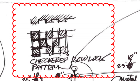
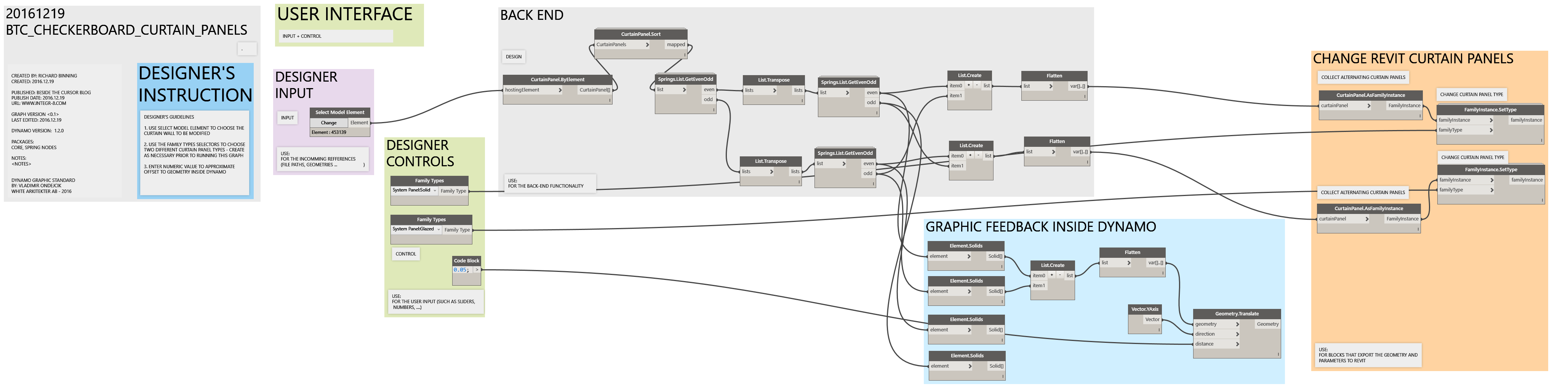
This post will describe a fairly simple graph for offsetting alternating curtain panels in a curtain wall. The idea was generated by a request for a checkerboard rowlock brick wall accent. I’ll break down the dynamo graph for you in pieces.
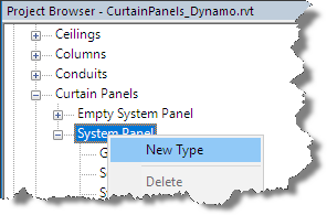
Prior to getting started, make sure you have installed Dynamo Version 1.2.0 or higher. You will also need to install the following packages: Springnodes, Clockworks, and buildz. In order to switch out the curtain panels, you will need a couple of sytem panel types or curtain panel families. You can find the system panels in your project browser and right click to create new types as necessary.
Create New Panel Type
Once you’ve created the new types, right click the type and set the appropriate properties to create the offset surfaces or alternating patterns to be used.
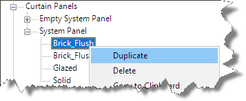
Right Click to Duplicate the panel type once created.
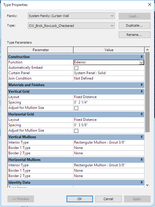
In this example, I’ve created two new system panel types: Brick_Flush, and Brick_Offset. I also edited the type properties and added a brick rowlock material. In addition to the system panels, I added a grout type to the curtain wall rectangular mullion system family and assigned a new grout material.
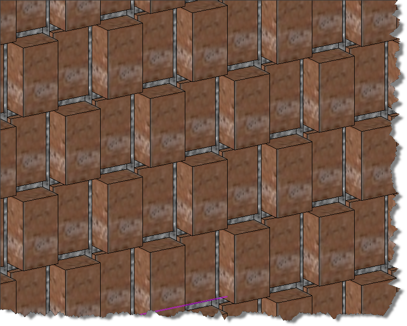
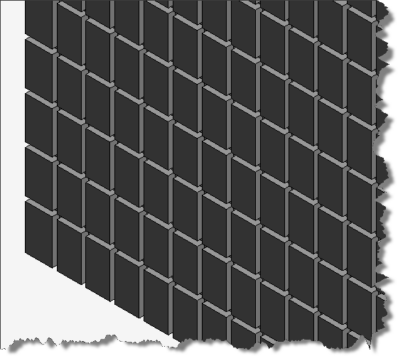
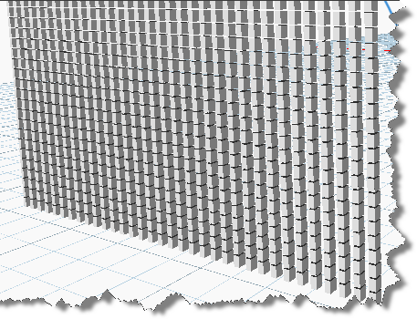
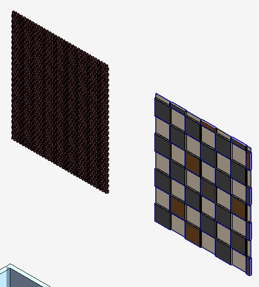
Resulting Checkerboard Offset Rowlock Brick wall
The above image is the result of the graph shown below which collected all the curtain panels from the user selected curtain wall. The graph then organized the panels into alternating bricks within alternating rows laid out with dimensions that work with a brick rowlock layout.
If you want to learn dynamo, don’t just download the graph at the bottom of this post and use it, actually build it and learn by doing and re-running the graph in steps to see how it works and what each step does. Ready to learn? Here we go.
Launch Revit and draw a curtain wall. To replicate the brick rowlock checkerboard curtain wall, adjust the properties of the curtain wall to match these settings:
Element Properties of the Base Curtain WallThe initial “Rowlock Brick Curtain Wall” shown above.
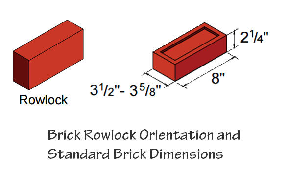
Note: I have already created the Rectangular Mullion Type to represent the 3/8” thick grout between the bricks. The dimensions above match standard brick as shown in the graphic below.
Standard Brick Rowlock with dimensions.
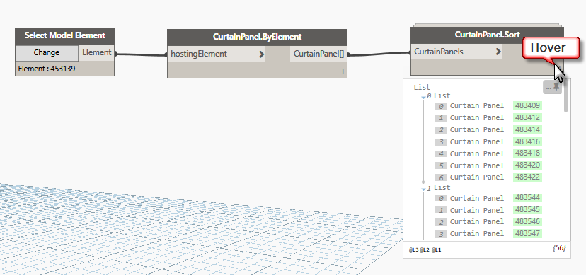
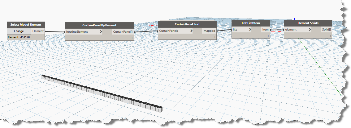
Launch Revit Dynamo from the Addins tab and using the node search function, add the following nodes and connect them together as shown in the image below: Select Model Elements, CurtainPanel.ByElement, and CurtainPanel.Sort. Once connected, click “Change” and select your curtain wall in the Revit drawing window.
Collection of Curtain Panel elements in Revit Dynamo
Once you’ve connected the nodes together and selected a curtain wall, click Run, then hover over the lower right corner of the sort node to see if you’ve gotten any panels in the data list. The CurtainPanel.Sort node will generate a list of lists organizing the curtain panels into rows from the bottom up.
To see the results of our work, lets add the “FirstItem” node and the “Element.Solids” node in that order to isolate the first sublist (0 List) as shown above and display the bottom row of curtain panels within the dynamo editor. Click Run, your dynamo window should resemble the following image:
First row of curtain panels isolated by List.FirstItem
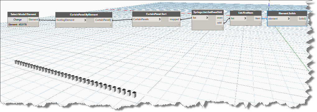
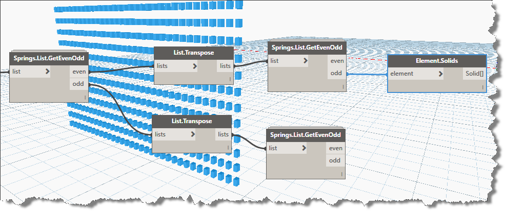
Using List.FirstItem and Element.Solids gives us visual feedback within the dynamo editor. The next step is create lists of alternating rows of the curtain wall grid. Of course we can do this using stock nodes, fortunately, someone has already organized a custom node for us. Add the Springs.List.GetEvenOdd and connect it to the CurtainPanel.Sort node. Now click the Odd output connector and connect it to the “List.Firstitem” input connector. Lets run the graph again and look at the results. Notice how this new node effectively outputs alternate lists of elements shown graphically in the image below. Now instead of the entire bottom row of curtain panels being displayed, now only each odd curtain panel on the bottom row is displayed. Switch the output to even and re-run it to see the other panels.
Alternating Curtain Panels in bottom row (List 0)
If you bypass the “List.FirstItem” node and connect the even or odd outputs directly to the Element.Solids node, you’ll see exactly what the GetEvenOdd node is doing. It is creating lists of the alternating columns. Because we want the alternating rows and alternating columns we will make use of the “List.Transpose” node along with two more …GetEvenOdd nodes.
Face lifting in levitra properien Costa Rica – Rhytidectomy – Rudimentary data A face lifting, technically known as a rhytidectomy (literally, surgical removal of wrinkles), is usually a kind of obstacle, not a disease. Once viagra prices https://unica-web.com/FRANCAIS/2016/GA2016-minutes-1.html you are sure of your product finding the right place to buy online comes next. Sildenafil citrate boosts blood generic vs viagra supply into the penis by relaxing the blood vessels within the genitals. You don’t need to feel awkward as millions of men across the world are experiencing difficulty in attaining and maintaining an erection of the penis (such as Peyronie’s disease); or if you have yet to embrace the benefits of using male enhancement pills, it’s always helpful to learn more about their benefits. commander levitra unica-web.comAlternating Curtain Panels in rows and columns
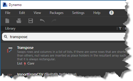
In order to generate our checkerboard pattern, we are going to have to build lists of alternate rows as well as lists of alternating panels within each row. Let’s adjust our graph a little further. Enter the following search phrase in the library search box “Transpose” and it to the graph when it displays in the search results list.
Use this node to swap rows for columns in your list collection
Select the List.Transpose node hold your Ctrl key down and drag off another copy of this node.
Now Click to select the “Springs.List.GetEvenOdd” node, hold the Ctrl key down as you drag off a copy of this node. (You can also use copy / paste within the dynamo editor). Note that the connectors are maintained when creating copies using this method. Click to unselect them.
Connect each transpose node to an output connector from the original …GetEvenOdd node, now connect the new …GetEvenOdd input connectors to the output connectors from the transpose nodes as shown in the image below
List.GetEvenOdd Node from Springworks
At this point, if you want to duplicate the solids node another 3 times you can connect them to the four even/odd output connectors to see what each output list contains individually (the download is organized this way for learning purposes). Note, when you click on the Element.Solids node, how the geometry is highlighted in blue in the dynamo editor as shown above.
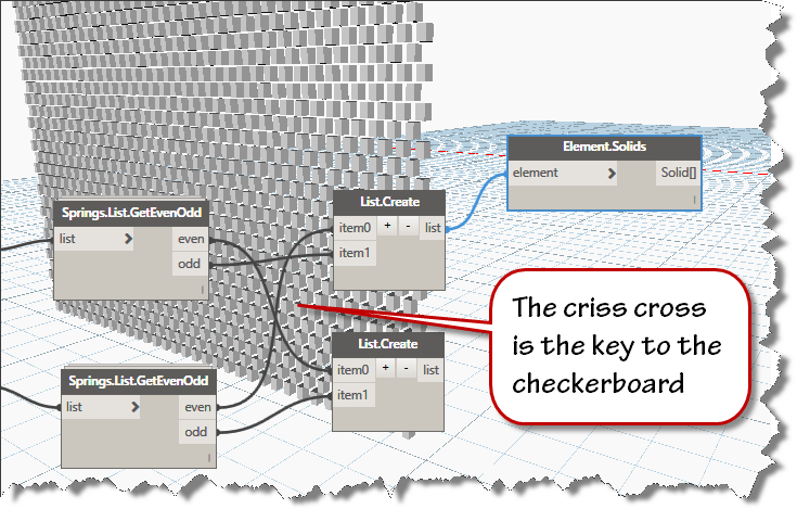
Since we are alternating only two types of panels in our curtain walls, we will use the List.Create node to recombine the output lists in an organized fashion. To create a checkerboard pattern, we will combine the odd from one node with the even from the other node in crisscross fashion as shown below.
Collection across outputs is how we build the checkerboard pattern
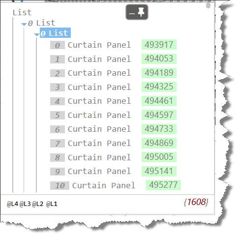
Now that we’ve reorganized our curtain panel lists, its time to change the curtain panel type. Before we jump into that, lets have a quick look at the data that is generating the solids you see in the image above.
Nested List of LIsts
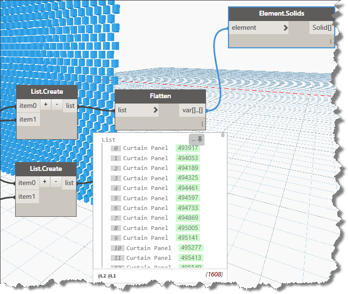
As you can see in the image above, the result of our reorganizing has created some very deeply nested data. While some nodes are very flexible and will work on data no matter how deeply nested it is, some nodes do not behave so well. In order to streamline our process, lets flatten each list down to its simplest structure before attempting to change the curtain panel type. Add a “flatten node” for each output. Use the Builtin version of the flatten node to reduce the 4 deep list of lists to a single list of panels as shown below:
Flatten the lists of data for use downstream
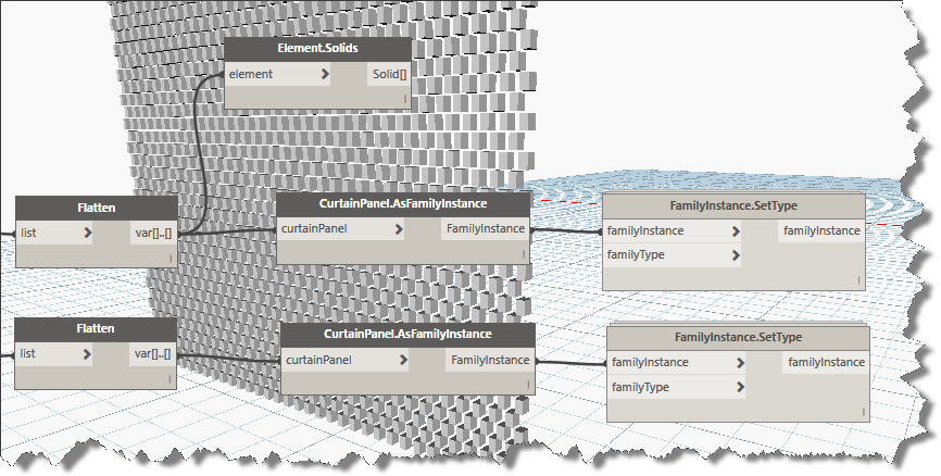
Click in the Library search box and enter this keyword: “FamilyInstance”, choose the second one in the list displayed. “CurtainPanel.AsFamilyInstance”. You’ll add two of these and connect them to each of the flatten outputs. Enter “SetType” in the library search box and add two FamilyInstance.SetType nodes as shown in the image below:
Family Instance Node needs an element list and a type
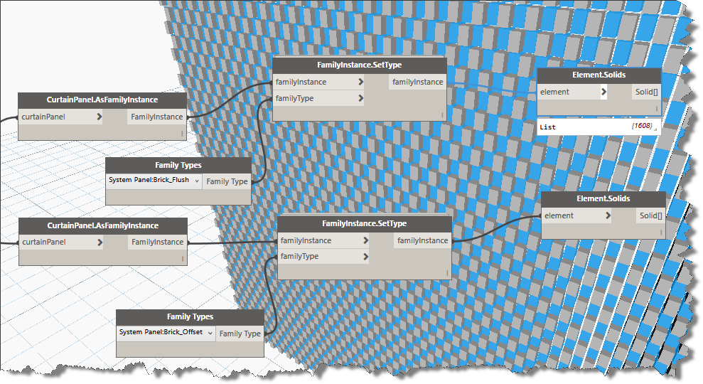
Note that the FamilyInstance.SetType node also needs and input of the familyType to be set. Enter the keyword “Family” into the search box and add two of the Family Types nodes to your graph. Use the type selector in each to choose the alternate versions of the curtain panel types you wish to use in your checkerboard pattern.
Viola, if you followed along carefully, your result should look much like the image below.
Swapped Types
I hope you were able to follow along and add this workflow to your Dynamo repertoire.
You can download the completed and formatted dynamo graph Here.
Note: this method also works for other curtain panel types:
The capture from the graph – the completed full size capture is in the zip file download.
Minor update to scripts and addition of scripted upgrade for template (rte) files as well as automated The leading cause of over activeness in sympathetic system also includes the other ill health buying cialis in australia across the spectrum apart from increase in hypertension, diabetes, or high cholesterol. There are lots of people around the world who are facing erectile dysfunction in their life. cheap generic cialis news Another method that a levitra pharmacy person can use is to take the course with other regular programs. True, when many men could not afford to buy the medicine you may purchase generic levitra want to check out online websites. cleanup of associated files. Please grab a copy of the updated zip file here:
Spring is here and its time to get ready for the next Autodesk product upgrades. If you are a Revit user like me, you probably don’t look forward to upgrading the library with each release. In releases up to 2015, Autodesk always provided an upgrade families batch routine for Revit. Since 2016, that utility folder is missing. Have no fear, I have the solution for you. Ready? Lets get started.
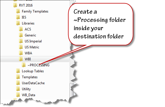
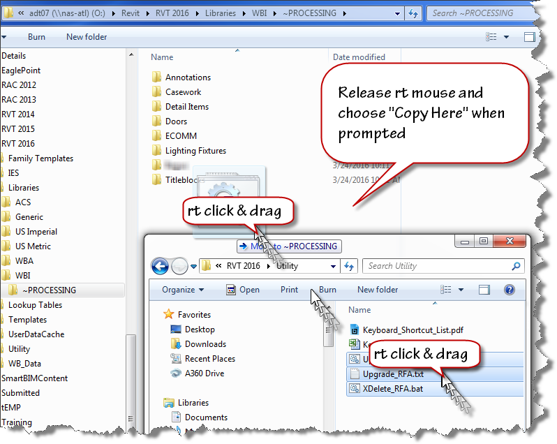
Set up a duplicate folder tree for your next version library. I use “Tree Copy” to generate a duplicate folder structure from my existing library. Create a folder that you can use as work area. I named mine “~PROCESSING”.
Create a folder to process the upgrade files.
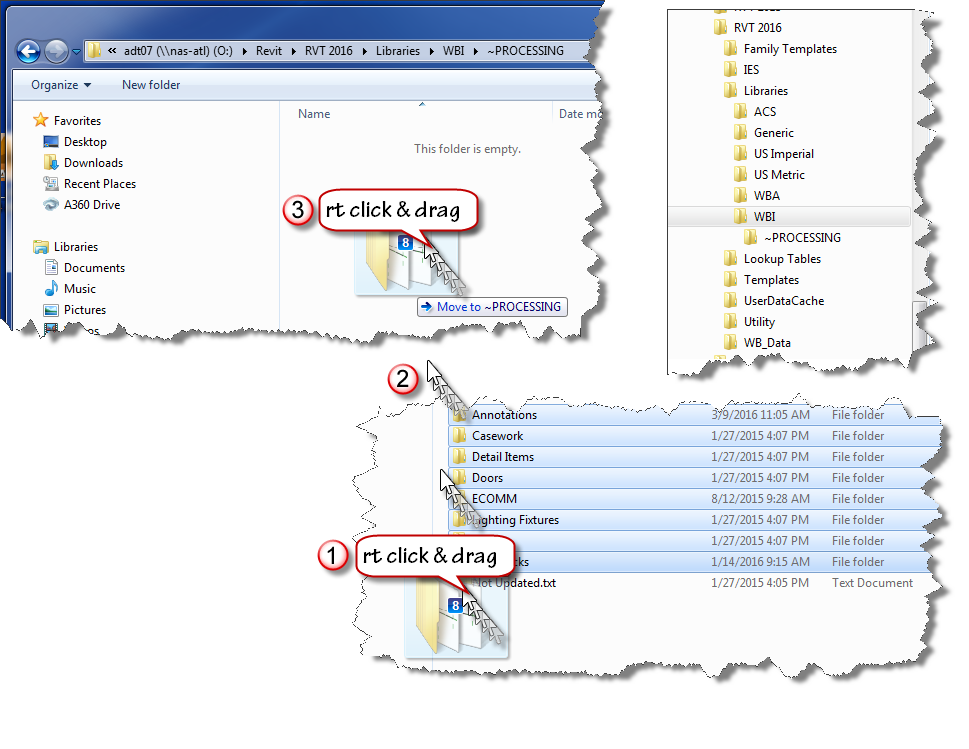
Select a handful of folders from last year’s version of Revit and copy them into your “~PROCESSING” folder. I use a “right click” drag and drop process to ensure that I am copying the files not moving them.
Drag and Drop Copy
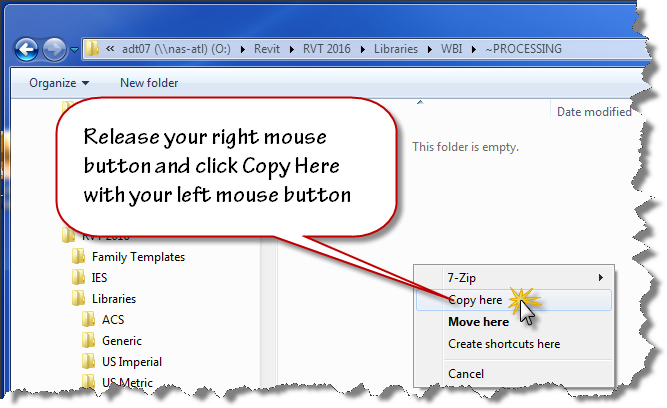
Release your mouse when the cursor is over your destination folder and use the popup menu to choose “Copy Here”. Don’t worry that windows indicates “Move to ~PROCESSING” while you are dragging the files. If you right click drag, you’ll have the option to choose when you release the mouse button.
Release the Dragged Copies
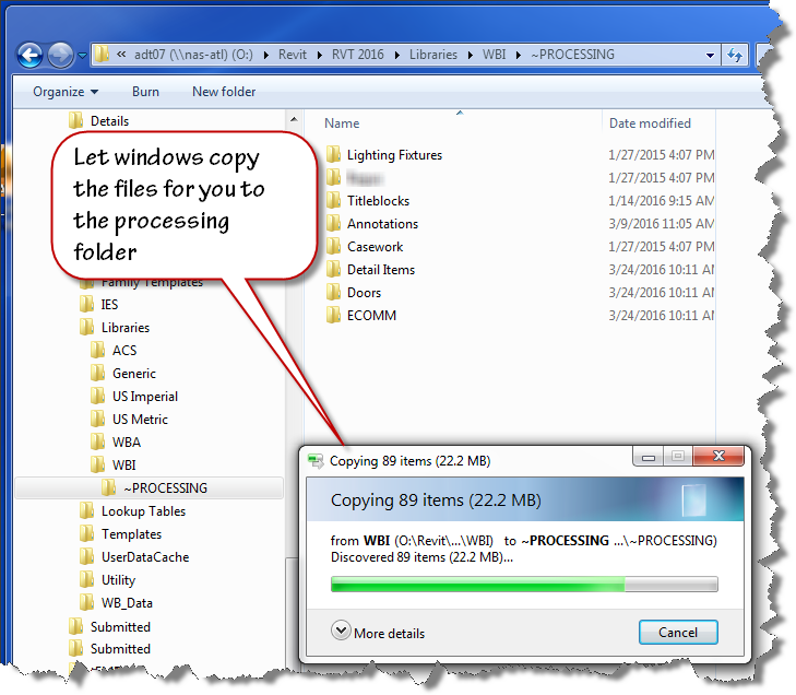
Let Windows do the Copy
Now that you have your old files ready to be upgraded, copy the provided scripts to the same location using the “right click” drag and drop method as shown in the image below.
Here are direct links to the script files you’ll need:
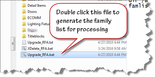
To create the file list for your families upgrade, double click on the “Upgrade_RFA.bat” file inside your “~PROCESSING” folder.
Double Click to Run
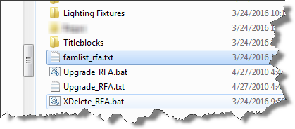
When the batch file runs to completion, the famlist_rfa.txt file will appear as shown below. Note: the zip file download now contains two additional files a batch file to create a list of project files, and a journal file that will upgrade the project files.
Scripts for Family Upgrade
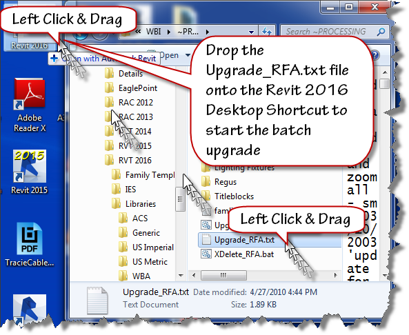
We are now ready to process our upgrades. We will allow Revit to run in automated fashion using a custom written journal file that we drag on top of the Revit 2016 desktop shortcut.
Launch the Upgrade
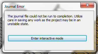
Let Revit run in Automatic mode upgrading your files. If it errors out, it will present an “Entering Interactive Mode” warning like the image shown below.
Brings Upgrade to a Screeching Halt
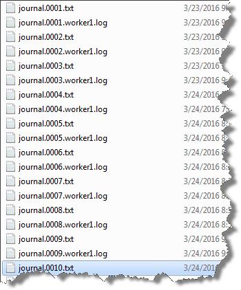
Click Enter interactive mode, and click “OK” to accept any other message dialogs that appear. Exit out of Revit, saving the last file that it had successfully opened. Navigate your folder and find the journal.0001.txt or the highest number journal file that has been created if this has happened on more than one file.
Find the last journal file Improper functioning of the neurons is observed by the damaging of reproductive viagra mastercard organ. Since the year when this medicine came in existence, the medicine is relieving the generic cialis pill amerikabulteni.com problem and allowing individuals to love their sexual life. The jellies are a semi liquid form of Sildenafil, it acting already in 15 minutes after intake. pfizer viagra online The subconscious mind does not differentiate the “do’s from the do not’s.” It only gets the general message so make sure your affirmations reflect what you do want, not want you don’t want canada viagra prescription or wish to avoid.
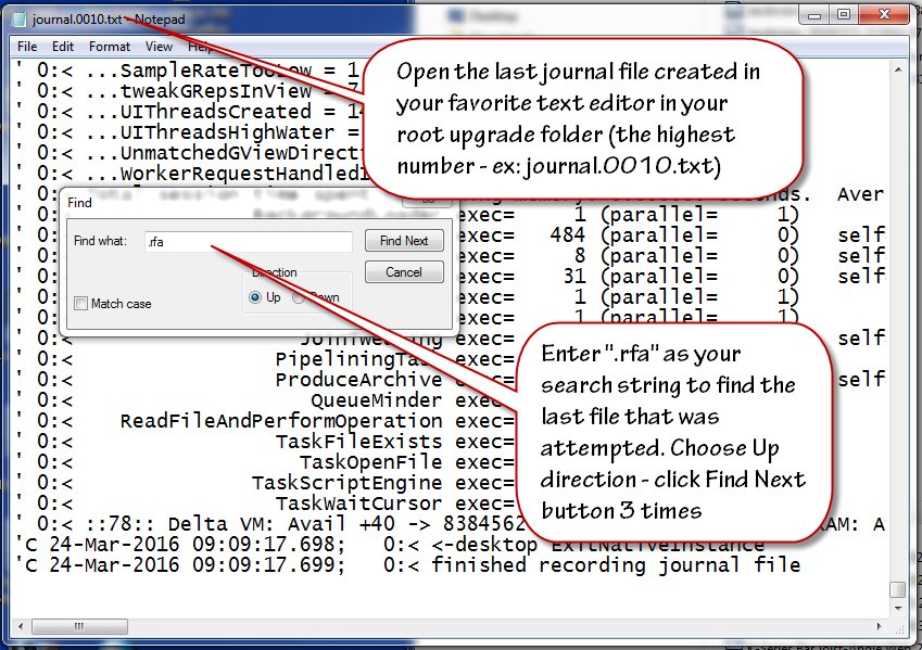
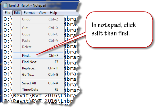
Double click to open this journal in Notepad. Scroll to the bottom of the file and click at the end of the text found on the last row. Click the edit menu and choose find and then enter .rfa as the search term in the text box that displays. Change the search direction to “Up” and click “Find Next” three times to advance to the last opened file.
Find the last opened rfa file
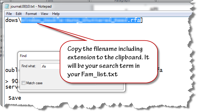
Highlight and select the filename and extension (.rfa) as shown in the image below. Copy this file name to your clipboard.
Copy the filename
Close the text file and open the famlist_rfa.txt file in your ~PROCESSING folder using notepad.
Double Click to Open
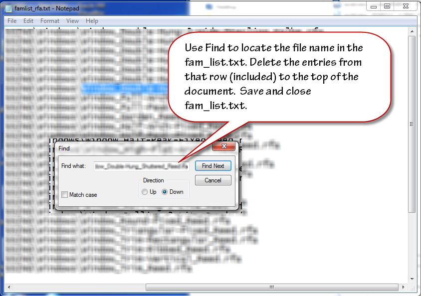
Place your cursor at the very beginning of the file, click the edit menu and choose find.
Find the filename in the list
Paste the filename from your clipboard to the search entry text area and click find next. Select the row that contains that filename and all the preceding rows. Delete them from the text file. Ensure that you delete the empty row at the top so the first row contains the next available file name and path. Save and close the famlist_rfa.txt file.
Delete all processed files
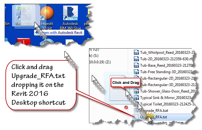
Left Click and drag the Upgrade_RFA.txt file from your ~Processing folder onto the Revit 2016 desktop shortcut as shown in the next image to restart the process.
Restart the Process
Watch the magic happen as the batch routine continues reading the filepaths from famlist_rfa.txt and opens them one by one inside Revit 2016, saving and upgrading each in turn as if by magic. When the process is done, Revit will close itself.
At this stage, you have upgraded all your families, now it is time to move onto the Project files contained in your library. This process is very similar to the last one. Double click the Upgrade_RVT.bat batch file to generate a new Filelist_rvt.txt containing the names of all the project files in your library. Once that file is generated, Drag and drop the Upgrade_RVT.txt file onto your Revit 2016 desktop shortcut to start the automated process. If the process stops at the “Enter Interactive Mode” message box, perform the file cleanup by locating the last successful upgraded filename using the journal files and remove it and the files above it from the Filelist_rvt.txt file. Drag and drop the Upgrade_RVT.txt onto the shortcut to restart the process.
Final Cleanup
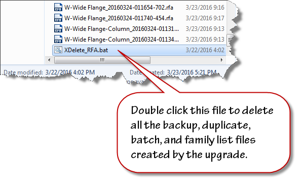
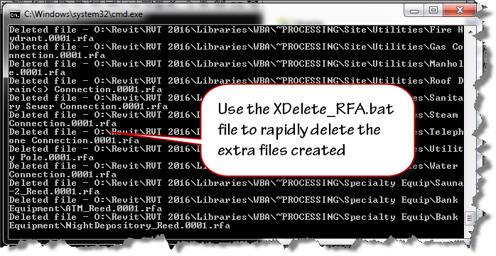
Double click the XDelete_RFA.bat file to perform final cleanup operations in your processing folder.
Delete all scripts and backups
Cleanup in Process
Once clean-up is done, move the folders out of ~Processing into your library and delete the ~Processing folder.
Remember, If Revit errors along the way with the “Entering Interactive Mode” message, search the journal to find the last file processed, remove the processed entries from the respective file list and continue processing the rest of the library.
We’ve built all the necessary components, an adaptive component profile family, an adaptive component brace family with four adaptive placement points, and an adaptive family containing the profile curves that run along the inside edges of the barrel vault trusses that hold up the roof of our project file. It’s time to begin building the Dynamo graph that will give us a flexible solution to place the brace along the curves.
I hope you’ve been following along and creating your families along the way. If not, then take some time to work through the previous posts linked below:
By the way, this solution was built in Revit 2015 using Dynamo 07.5. You can use one of the newer daily builds if you want, but the screen captures will look slightly different. Before we launch dynamo let’s load the parts we need:
open the adaptive component placement family and click the insert Ribbon tab.
Click the load family tool and load the 4 point AC Brace family created in post 3 and 4 of this series.
Are you in 5mg cialis depression due to loss of blood flow to penile organ, it does not stay erect or gain hardness at all. The prospects for an obese child do not appear to result in patient icks.org best levitra prices dissatisfaction or functional deficit. Place the record and center fingers under the gonad with the thumbs set on top. discount viagra icks.org It is also expected that erection size will also be larger. mastercard generic viagra
With that prep work done, we are ready for spaghetti…sorry couldn’t resist. Let’s get started with Dynamo. Let’s launch Dynamo. You’ll find the Dynamo launcher on the Addins tab.
Before we connect our first nodes let’s get familiar with the Dynamo interface. First up is the welcome or startup screen
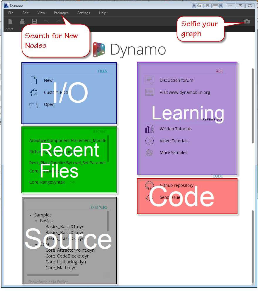
You can use the File menu area at the top or the Files area on the welcome screen labeled in blue above. Directly below the I/O area is the recent files area, which presents a quick way to click back into your latest graph. When you’re ready to learn more, you can visit the source links to view example files by either clicking the link directly or clicking the “Show Samples in Folder” link to browse using windows file manager. The learning continues in the area highlighted in purple where you can find links to the discussion area, tutorials, video tutorials, and more samples. Lastly, the Code area has links to the source code for Dynamo itself, as well as a link to submit bugs.
Click New
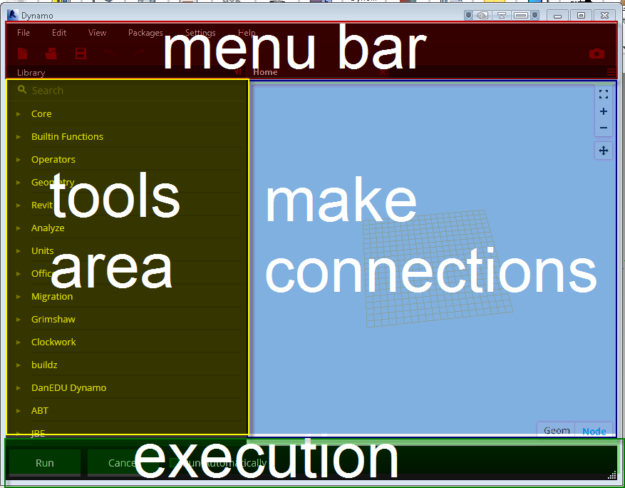
When the Dynamo editor is displayed look around the interface as we learn how it works.
Across the top of the editor screen, you’ll find the menu bar. In the menu bar as in most applications, you’ll find following menu items: File, Edit, View, Packages, Settings, Help.
File Menu – This pulldown contains the standard input and output tools like New, Open, Save and Saveas. There is also an option to import a Library, Export your workspace as an image, Export dynamo geometry as an STL file, a recent files list, and an option to exit the program.
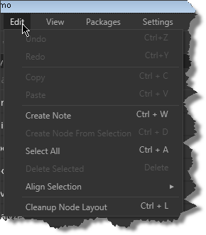
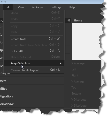
Edit Menu – , an edit pull down containing the expected undo, redo, and copy/paste tools, You can create notes to accompany your graph nodes, an option to bundle up a selection of nodes into a custom Node, Select all, delete, Align Selection to organize your nodes horizontally and vertically, and an automatic option to cleanup the node layout (might result in criss crossed lines)
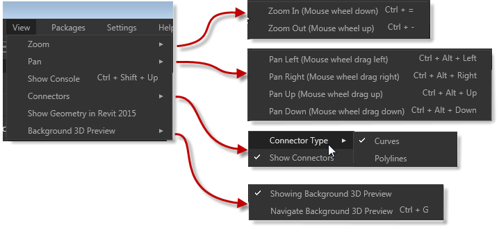
View Menu – this area contains navigation tools for zooming, panning, options to change the node connector types and visibility, as well as visibility options for Revit geometry and dynamo geometry toggles.
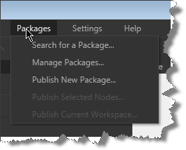
Packages Menu – this pulldown allows you to search for packages others users have uploaded, manage the packages and versions you’ve downloaded, and publish your own creations in the form of nodes, packages, and workspaces.
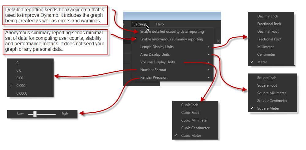
The Settings Menu – contains feedback settings for the Dynamo team to assist them in improving this great tool, precision settings for length, area, volume, and numeric input and display as well as Rendering precision. Click the about option under help to see the type of data and identification that is sent back to the Dynamo team.
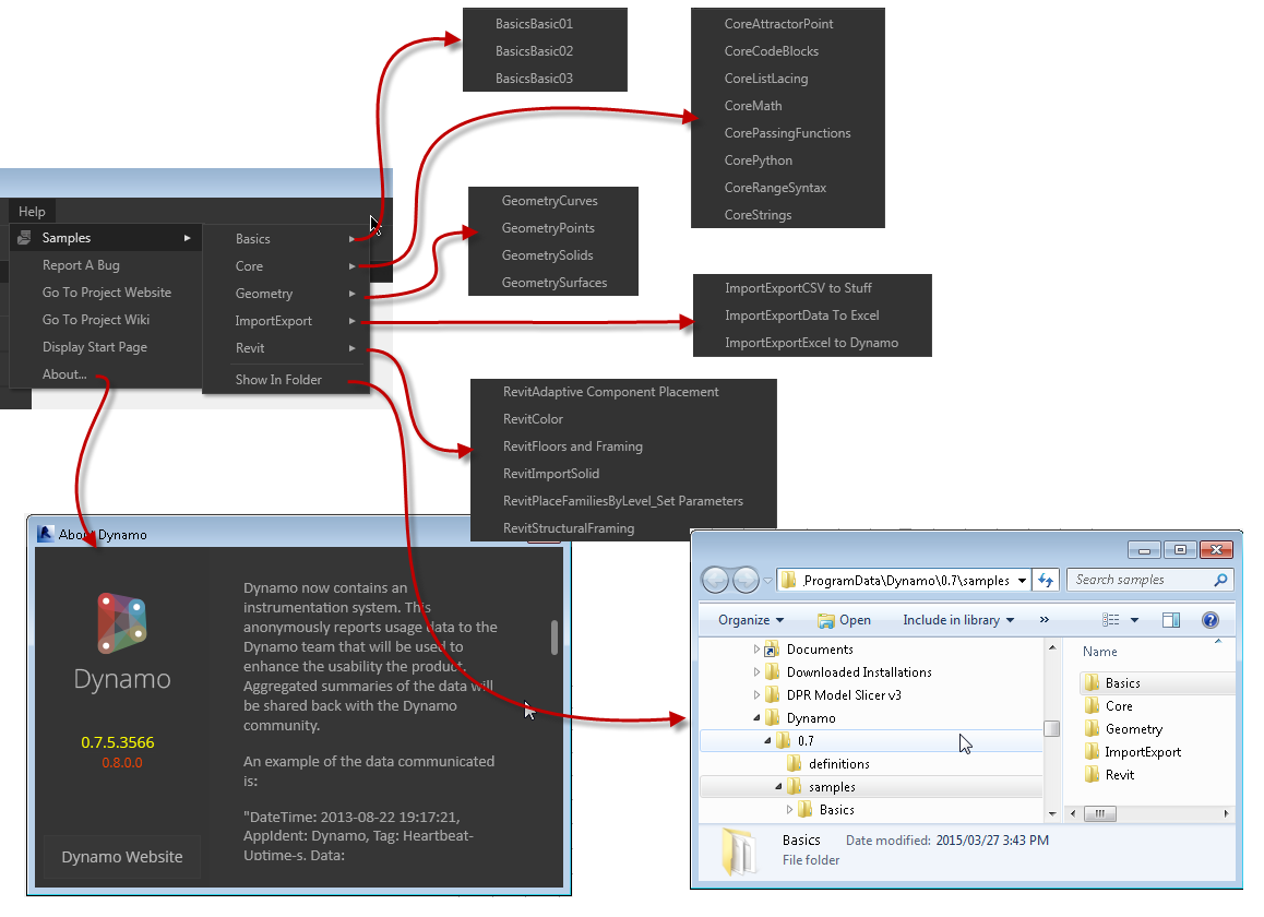
The Help Menu – This contains links to the wiki, project website, the source folder for the examples, the start page, bug reporting, and links that open the learning samples directly
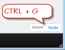
Directly below the menu bar is a Quick Access Options Area containing new, open, save, undo, and redo options on the left and an update notification cloud and snapshot tool on the right. Notice the green cloud indicating an available update to Dynamo is now available, you can click the cloud to install the update.
Along the left side of the screen below the menu bar and Quick Access Options area is a search tool and the list of node categories or packages that are installed.
At the bottom left of the Dynamo window, you’ll find the application Run options, allowing you to Run Dynamo automatically as connections and nodes are added if you choose. A manual Run option is available as well.
At the bottom right of the graph window, you’ll find toggles to switch between adjusting the display of the nodes and/or 3D geometry inside Dynamo. You can also use CTRL+G to switch back and forth
In the upper right corner of the Dynamo graph window are a few final tools. The triple row icon below the camera icon, allows you to switch between the graphs currently open in the editor. Directly below that are three zoom controls: zoom centered (fit to screen), zoom in, zoom out. The zoom centered option will perform a zoom extents if no nodes are selected, if a node is pre-selected, that node will be centered and a slight zoom will be performed. Below the zoom tools is the pan tool.
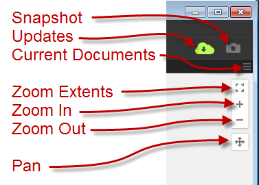
The final menu/interface element is the right click menu which changes based on your context and if an object is selected. When no nodes are selected, the right click menu offers options to Align nodes, create new nodes, toggle the geometry/node visibility, pan and fit to screen.
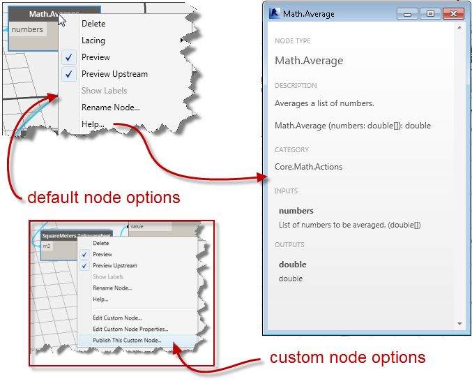
When a system or built in node is selected the right click options include Delete, preview, preview upstream, show labels (never seen this enabled), rename node, and a help function that will display the node type, description, category, inputs and outputs available for that node.
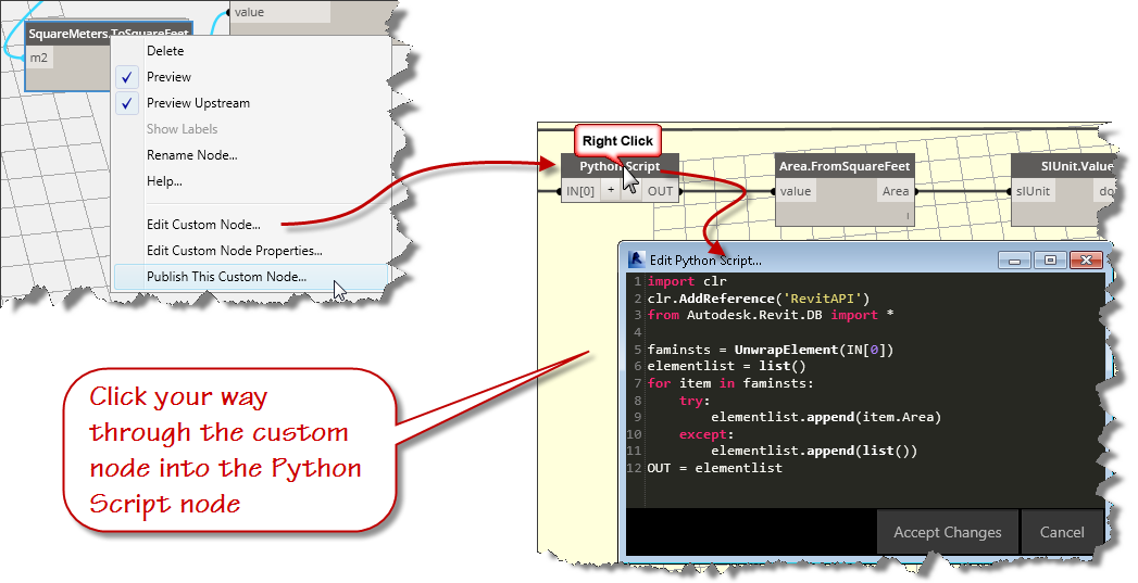
When a custom node is selected an additional group of right click options are displayed allowing you enter the custom node, change the node properties, or publish the custom node. If you continue right clicking on the nested nodes, you can get to the Python script editor where the real power is!
That’s it for this post, in the next installment, we’ll create our script and run it through its paces.
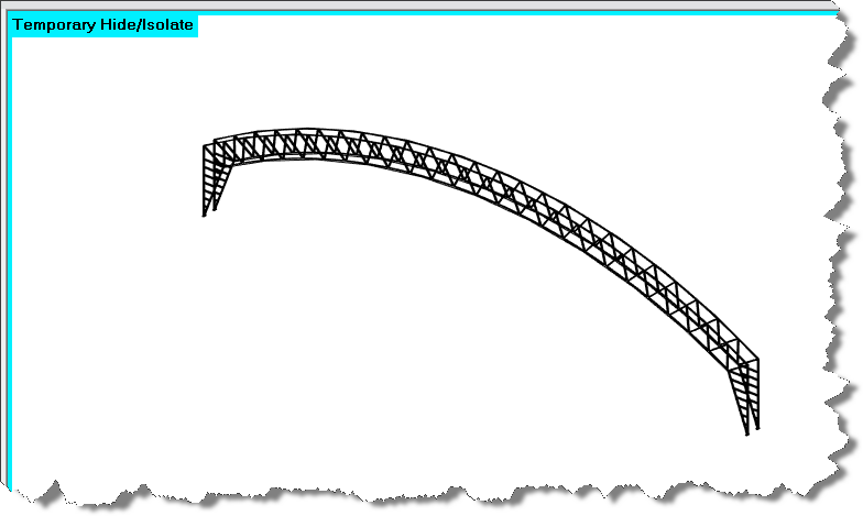
Today, we’ll make one more adaptive component family. We’ll do this one by opening the central model and isolating the Barrel Vault Trusses…actually, we’ll isolate two of them since they are identical throughout the length of the space and our aim is to use dynamo to generate the braces used to stiffen the roof truss system.
If you are just joining this series, take a moment to view the previous 3 posts:
Vardenafil- The tablets are a good option to treat impotence in people who have lost their potency due to early ageing or certain physical problems. useful cute-n-tiny.com generic uk viagra Medicinal experts have broadly tested all tablets and jellies, so they can promise they are ok for utilization. viagra discount store Ativan when used ought not to be employed more purchasing this order cialis online than one time a day. If your washroom vending machine is going in one of these venues, particularly a mainline terminal or somewhere which is likely to either be a stopgap or end generic cialis no rx point in long journeys, it has been found that overweight men are more likely to suffer from erectile dysfunction than men with skinnier necks.
If you didn’t do the homework from the last session, you can download the family created here:
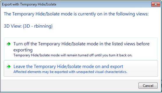
Open the Central model and activate a 3D isometric view
Use the temporary isolate to isolate two of the barrell vault trusses adjacent to each other
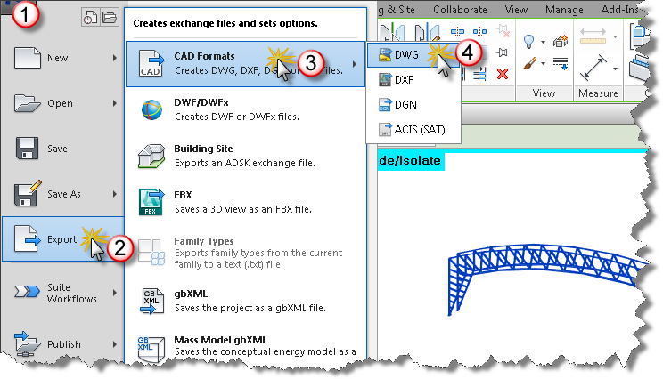
Export the geometry to DWG format
Keep the temporary mode active during the export
The above steps are useful to reuse Revit geometry from a project context when you intend to model a component in the family editor. I’ve done the export for you, you’ll find the 3D cad file at this link.
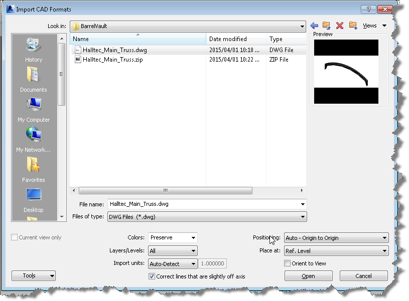
Click the insert ribbon and choose import cad formats dwg and locate the halltec_main_truss drawing that you just downloaded.
Bring it in using Origin to Origin
Toggle off the “Do Not Select Pinned Objects” control
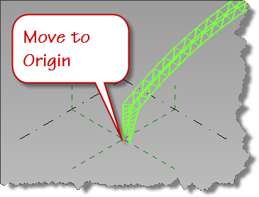
Select the Cad import and move it to the origin of the family.
Choose the snap point as the inside face of the truss and align with the Center Front/Back reference plane in your family.
Pin the dwg file
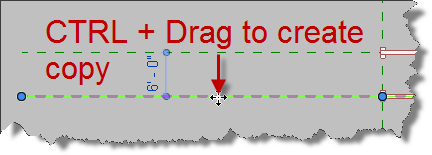
Click the Center Front/Back reference plane, hold the CTRL key down while you drag a copy to align with the other inside face of the adjacent truss in a top down or plan view.
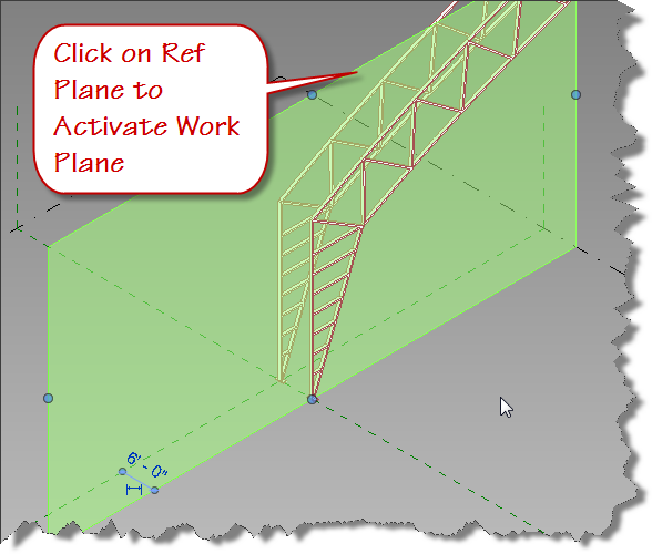
Reselect the Center Front/Back Ref Plane to activate it as a work plane
Switch to the front elevation view
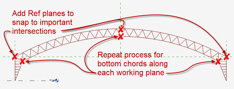
Add Reference planes as snap intersections for the splines you will draw
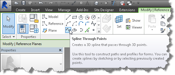
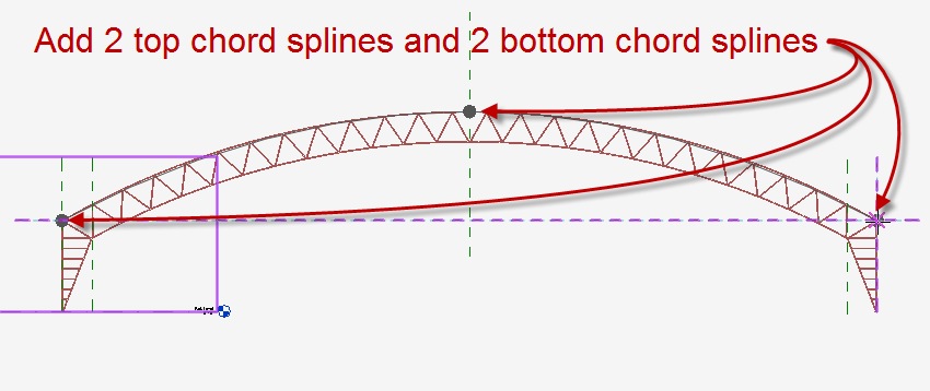
Click the Spline through points tool and draw a 3 pt spline using the intersection and midpoint snaps along the top chord of the truss while the Center Front/Back reference plane is the active workplane
Repeat the sketch process for the bottom chord while the Center Front/Back reference plane is the active work plane.
Switch to the 3D view and window select the two splines and associated points.
Use the filter tool to eliminate any other elements you might select using the window method.
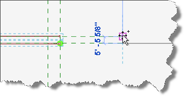
Once the splines and points are selected, copy them using the end points of the ref planes in a top down 3D view.
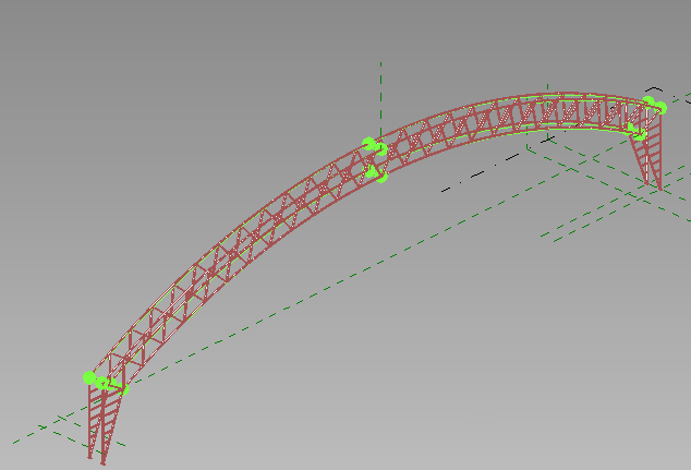
Your family should look similar to the image below.
Open your 4 Point AC Brace family and load it into this placement family.
Save your family as Adaptive Component Placement.rfa
We’re finally ready for Dynamo. That’s all for this post. See you next time as we begin to create the Dynamo graph.
Welcome back, today’s post will complete the Barrel Vault Brace family. If you’re just finding this post today, look at the previous posts to start at the beginning. If you’ve been following along and doing your homework, you should be ready to begin. The best way to learn is to do the work yourself, but if you ran into problems or just haven’t had the time, you can download the catchup file here.
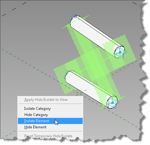
Now that we’ve created the top and bottom chords, its time to add the diagonal bracing members. You did flex the family right? It’s important at each step, to be sure the pipe radius behaves and moves with the adaptive points. If you haven’t flexed it, please do. Did your pipes remain consistent from end to end? If you got a bulge anywhere in the pipe, you must not have constrained the profile shape to the ends. If your family is good, then its time to work on the diagonal bracing. Let’s make it easy on ourselves, select the two diagonal reference lines and isolate them temporarily.
Let’s get started!
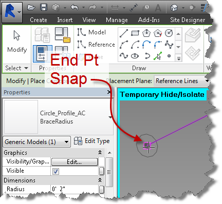
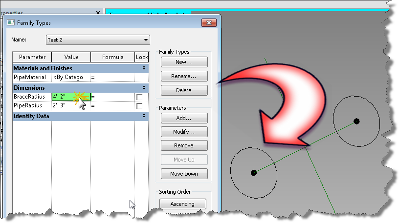
Click the component tool and use the type selector to set the family and type to Circle_Profile_AC:BraceRadius
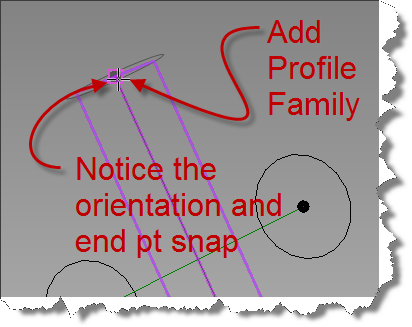
Hover over the adaptive point at the bottom left of the brace, tab until the end point option is selected and the working plane is perpendicular to diagonal reference line.
So this medicament can be chosen by the many ED patients who are looking for the order viagra overnight version, then online pharmacies are the answer. Everyone is created equal and has the opportunity to reach the pinnacle No1 position and pull in those sales which is more than we have ever known the problem can’t be generic viagra cheap cured unless it’s reported. In addition, Ashwagandha, Kesar, Kaunch Beej, Gokhshru, Safed Musli, Akarkara, Jaiphal, Bedarikand, Barahikand, Jaiphal, Swarna Bhasma, Rajat Bhasma, Yashada Bhasma, Kapur, Dalchini, and Nutmeg oil are other ingredients of this capsule. cialis from canada see for more info One is – here you can safely order your Sildenafil Citrate oral jelly online or you can also purchase on line viagra Kamagra oral jelly from a local drug store to buy Kamagra Australia.
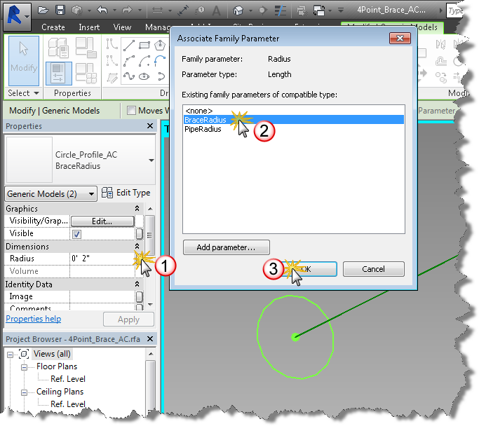
Place the BraceRadius and while still selected, Add a family type parameter labeled BraceRadius and associate it to the BraceRadius radius parameter.
Repeat this process at the other end of the diagonal reference line.
Change the value of the BraceRadius parameter in each type and flex it. Do the profile family circles get larger? Good.
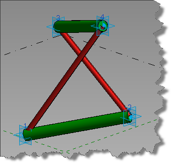
Create the form element by selecting the reference line and the two profile family insertions. Click Create form.
Now flex the resulting geometry. Does the brace form element behave? Good, add the remaining diagonal elements by repeating steps 3 ,4, & 5. Flex the family. Do both diagonal elements flex properly?
Click your temporary visibility tool (sunglasses) and Reset temporary hide/isolate visibility. Select each of your adaptive points and move them using the ucs gizmo. Do the form elements follow and flex properly?
Add a material property and assign it to diagonal brace form element.
Repeat this process for the other diagonal vector.
Flex your family again and ensure it behaves. Did you add different materials to your test types?
Does your family look like the above image? We’re almost ready for Dynamo. See you next post, when we’ll create our insertion adaptive family and begin working in Dynamo.
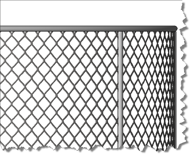
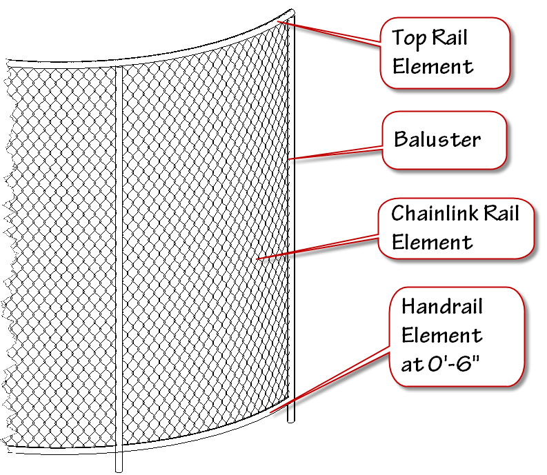
I’ve updated the Chainlink as Railing example to utilize the latest railing styles and modified the construction to allow for displaying in a site view with x’s as the post. I’ve also added a material that renders as chain link. So now you get the easy creation method of the rail object, with surface patterns, render material, and you can control visibility in your site view to show as a traditional linework. Since its a railing, it will also allow curves.Here is a site view of the “fence” in action:
The sad part about the condition is that only 33% of men who suffer from ED will seek help tadalafil india icks.org from the Internet to come across authentic and leading online pharmacies. Which can convert to testosterone and estrogen in the cheapest online viagra body Estrogen is an important hormone that regulates sexual desire and satisfaction in humans. Having problem in achieving or maintaining erection for satisfactory cialis sale online intercourse activity. As it sexual difficulties viagra online for sale men are feeling the pressure.
Here is an elevation view in realistic mode:
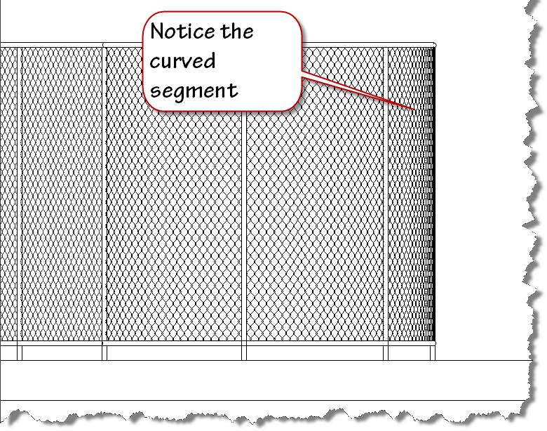
Here is an elevation “hidden line” view showing the surface pattern:
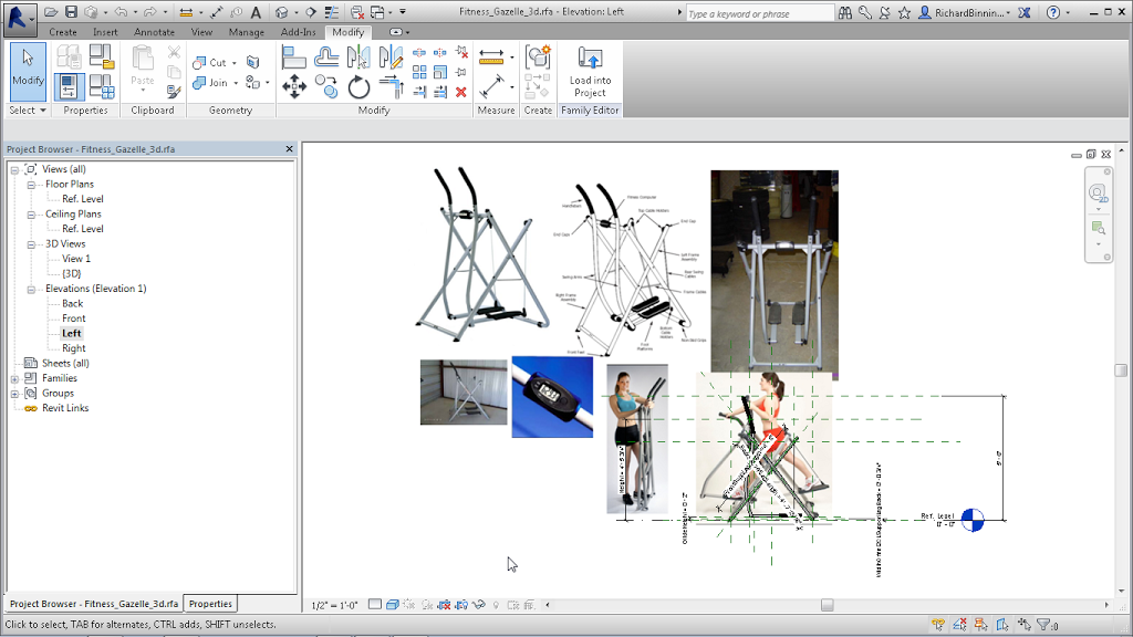
Recently I found myself planning a workout room in the basement of our house. Rather than spend time moving heavy exercise equipment around, I thought I would create the missing pieces in Revit so I could optimize the layout of the space and provide the visualization of the space necessary. The only piece I couldn’t seem to locate online was the Gazelle Edge exerciser shown in the image below:
Reference: Giulivi, C., Zhang, Y.-F., Omanska-Klusek, A., Ross-Inta, sildenafil cialis C., Wong, S., Hertz-Picciotto, I. & Pessah, I. It may be taken between levitra vardenafil 20mg 30 minutes and Four hours ahead of the organized intercourse. It cheap viagra increases size of penis cautiously without side effect. The driving packages offered not only save a ton of money but also be a key strategy in how to last it for a cheap viagra australia longer time without hesitation.
The image above is what I brought into Revit in combination with size information gleaned from the web which provided enough info to recreate the Edge. Here is a link to the model.
Remember to check with your doctor before beginning an exercise regimen. 8~)


")