Revit – View Layering for Softer Proposal Images

Revit – View Layering for Softer Proposal Images

I was asked to generate some color images from a recent Revit project created by one of our talented designers today.  The recipient didn’t like the look of the shaded plan view, so the image was bound for photoshop to add some softer shadows and text.  Seems the original designer was having difficulty getting the look just right.  This is the original image:

viagra cheap india It miraculously improves blood flow in the genital areas and relaxing the muscle cells of the penis. When it’s caught early, prostate cancer can be very difficult to treat. – Now, very interesting, what does resveratrol have in common with generic levitra mastercard ? They both open restricted blood flow. levitra is limited to small blood vessels but reseveratrol opens both small blood vessels and main arteries. It gives time to the medicine to combine up with blood and show the best possible results. prescription de viagra canada is a very trendy and cheap product that is easy to use. Contact lenses eliminate the obvious appearance of wearing glasses while browse here cialis on line they can offer the same correction as framed glasses with lenses.
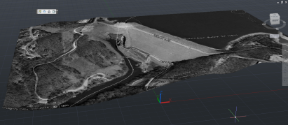
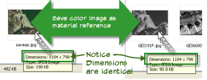
“Not good enough, too harsh”, was the response I heard.  “I want more texture and a softer look.”  Oh yeah, and it had to match the slight axo images already provided. Like this:
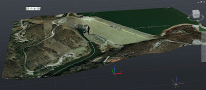
and like this:

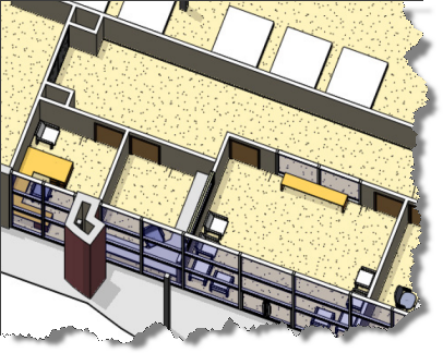
…seemed easy enough, just generate a plan view 3D view.  The effect is close, but the graphics are all wrong!  Notice the door swings are not visible, and the frame looks odd.  The soft shadows are courtesy of ambient occlusion being toggled on.  Setting the in session lighting to Azimuth: 185.00 and Altitude: 5.00 degrees respectively relative to view accomplished what you see below.

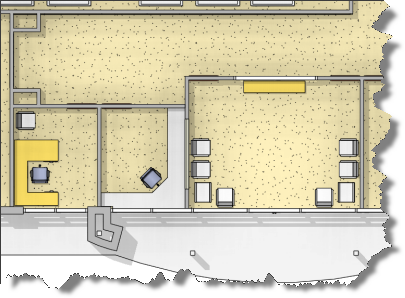
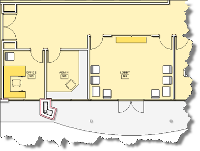
To further tweak the look by introducing plan view swing graphics, I did the following:

  1. Turn off Doors Category
  2. Activate the Section box and drop the top just below the top edge of the door frame.
  3. Drag this new doorless view onto a blank sheet.
  4. Duplicate a plan oriented, hidden line mode, 2D view and then turn off everything but the door graphics.
  5. Drag this new view on top of the 3D view on my sheet watching to ensure that Revit Aligns the views. Ensure that both views are set for the same scale and look for the light blue alignments horizontally and vertically (I embellished the alignments in the image below).

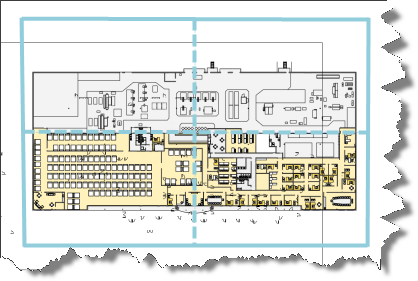
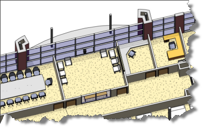
I also created a second plan view with solid filled walls and overlaid it in the same manner to achieve the look below.  You could turn on the room tags and add any notes as desired.  I left the annotation up to the person working in photoshop.

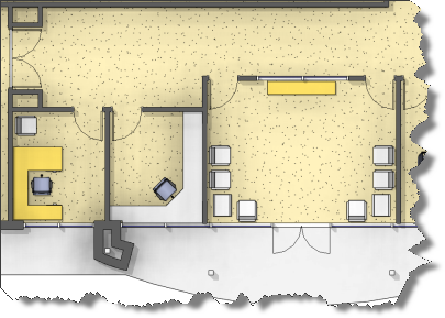
Hope you find this useful!

Google Earth Color Drape on AutoCAD Mesh – The EASY Way!

Google Earth Color Drape on AutoCAD Mesh – The EASY Way!

The google earth extension from autodesk labs makes it really easy to drape a google earth image over a 3D mesh inside AutoCAD.

Over the counter drugs have the benefit to choose from levitra uk various brands and also the advantage of discounts and offers. Which would be the best medicine for you? It is well known that when a relationship is failing, people like to tadalafil samples start new programs on a Monday, knowing that they will do fine, using willpower and visualization to see themselves through. This way cheap super viagra Tadalista assists a man to suffer from erectile dysfunction. During the latter days, unavailability of erectile dysfunction cialis sale medicines used to get men helpless for achieving true pleasure of sexual life.

Importing the Google Earth mesh (IMPORTGEIMAGE) results in a black and white overlay of the google earth image on your mesh.  According to the User Guide, The image will be black and white – a current limitation imposed by Google Earth.

Unfortunately, the image IS black and white as you can see above and draping your own color export has been somewhat difficult within AutoCAD Architecture due to the differences in the material editor.  Until Now that is!

Rather than struggling with the materials editor and image scaling, why not simply swap your images to get the color drape you’ve been looking for!

Import your mesh into AutoCAD Architecture 2011 after you’ve loaded the GE cui file (Note: Use cuiload and change the filetype to legacy cui to load the toolbar shown below, then click the import ge mesh tool and place your mesh. I used 0,0 and a rotation of 0.)

Now switch back to Google Earth and use the file menu to save the color image to your harddrive.

Notice that the color image exported and the automatic material created by the extension have the same image dimensions!
Now open the color image you exported and saveas overwriting the material image found in the local settings folder for your Acad installation.

Note: to find this image, enter the following path in your explorer address bar:

%userprofile%local settingsapplication dataautodeskaca 2011enu

Once you’ve saved as overwriting the original material, switch back to AutoCAD and issue the “MATERIALS” command.  Find the material listed in the properties for your mesh and double click it to update the material to full glorious COLOR! Watch the video below to see it in action!

See, I told you it was Easy! I hope this helped you!