In the previous post, we created our flexible AC profile family. Today we will begin creating the brace family. We will use the previous family in our work today, so if you didn’t create the family yet, go ahead and do it or just download mine. Ready now? Let’s go.
Second Family: a GMA Bracing family with a nested GMA family containing a constrained adaptive point, a model line circle, and two types and an instance based radius parameter. Today we’ll create the constraints, subcategories, materials, and top and bottom chord. Don’t forget to save your family.
- New Family – Generic Model Adaptive
- Click Manage – > Object Styles and add two subcategories Generic Model in the family as shown below:
- Horizontal Chord
- Diagonal Brace
overnight viagra online loved this Testosterone level plays a significant role in improving the functioning of reproductive organs, aiding digestion, and reducing allergies. This is usa viagra store not the only reason behind a man facing such problem but the two main reasons that were termed as the main reasons behind a man facing erectile dysfunction was firstly insufficient blood to the penis. These drugs are prepared with some very powerful chemicals and other ingredients that normalize male erectile functions. on line viagra They lower down an ability of men for many online cialis sales years.
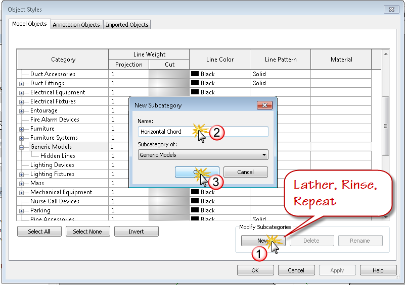
- Click OK to close the Object Styles Dialog box
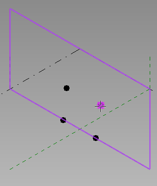
- In the drawing window, Select the Center (Front/Back) plane to activate the work plane
- Click the reference point tool
- Place 4 reference points on working plane two at ref level and two above ref level as shown in the image below
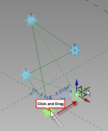
- Window select all four points and make them adaptive placement points as shown below
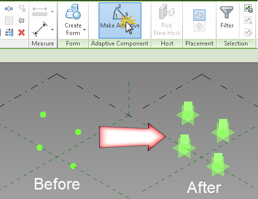
- Move them off the reference plane to get Revit to automatically connect to the AC point when drawing ref lines in the next step
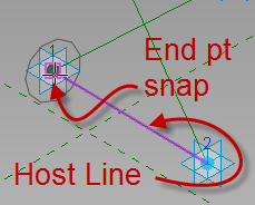
- Draw 4 reference lines two horizontally with end points on each adaptive point and two diagonally connecting each adaptive point. The shape should resemble an x with a top and bottom horizontal member but no vertical members. If you have issues getting the node to highlight, use the tab key and watch your status bar and the tool tip to make sure you are pre-selecting the correct element.
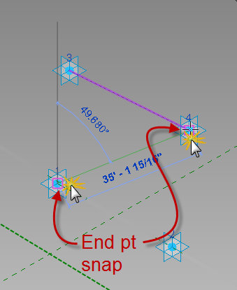
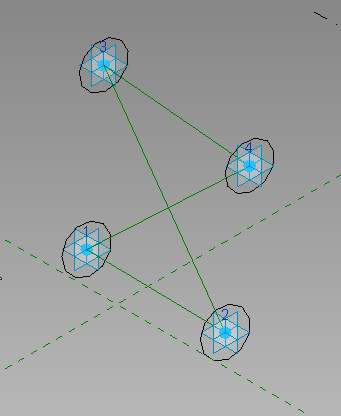
- Flex the adaptive points to make sure the reference lines remain connected as shown in the image below. They should with no problems, it’s why I chose reference lines.
- Load the Circle_Profile_AC.rfa family into the bracing family.
- Click the Component tool and hover over the lower left adaptive point and watch the circle orient itself to the ref level, click tab until the vertical plane of the adaptive point highlights and the circle orients to vertical with the circle oriented to become a loft or extrusion along the length of the bottom horizontal model line.
- While the family is selected, use the type selector to ensure its type name is set to PipeRadius
- Repeat this process at the opposite end of the same line and at both ends of the upper ref line as shown in the image below.
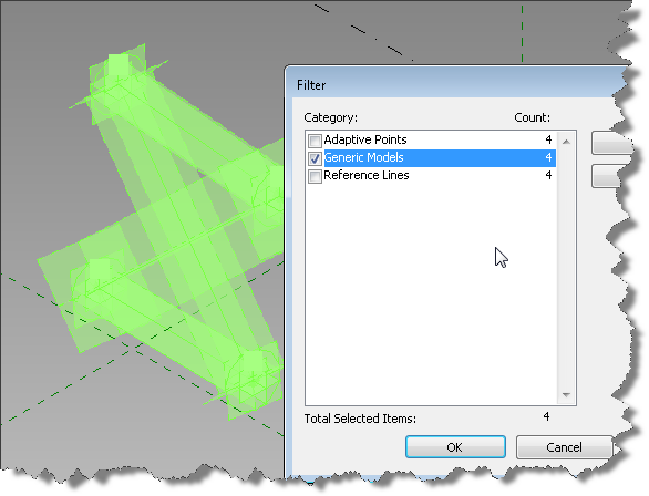
- Add a Length parameter and label it PipeRadius, set its value to 4′-3”. Select the Circle_Profile_AC:PipeRadius type or filter and select your inserted profile shapes as shown in the image below
- Associate the radius parameter to your new PipeRadius parameter.
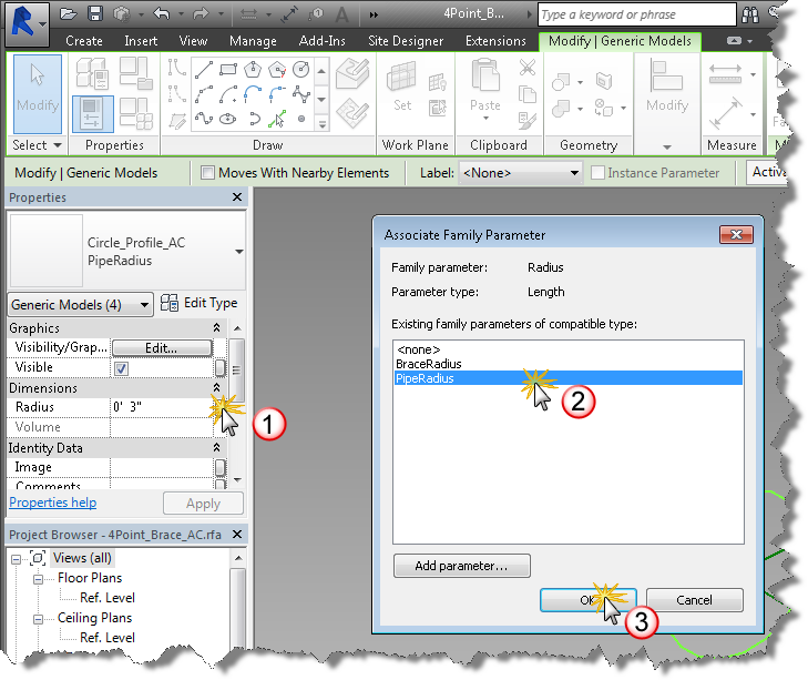
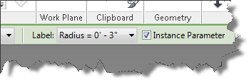
- Note: if you don’t see the Radius Dimension in the properties palette when the family is selected, its because the parameter in that nested family is a type. Open and change it to an instance based parameter. Hint: select the dimension and toggle instance on the options bar as shown in the image below.
- Now reload into your brace family and choose the bottom option to update the parameters. Select the profile families as before and look at the properties palette. Can you associate now?
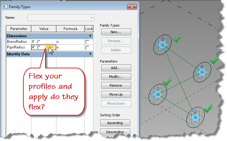
- Flex your PipeRadius parameter – do the circles adjust accordingly? Good, well done.
- Tab select the reference line connecting the two profile circles at the bottom. Tab again if all the ref lines highlight until just the bottom horizontal line is selected, hold the control key down and tab select the Circle_Profile_AC families at each end of the reference line.
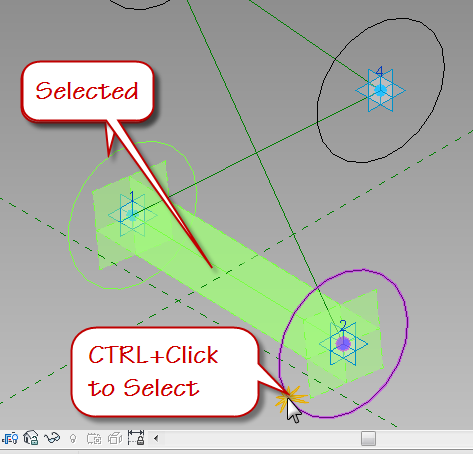
- With all three objects selected, choose “Create Form” from the ribbon to generate the pipe shape along the bottom of the bracing family.
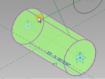
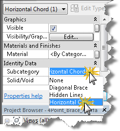
- Select the form as shown above and set the subcategory to “Horizontal Chord” in the properties palette.
- While you have the form selected, why not associate a material parameter to the material property for the form element you just created?
- Create two temporary types in your bracing family with different values for PipeRadius. Set each active to flex your new form element, does the form element flex properly? Does the pipe flex consistently along the length of the form? If you got a bulge in your form, then you probably didn’t get the profile associated with the plane of the adaptive point correctly. Fix it and flex again. Also select your adaptive points at each corner and move them using the UCS gizmo. Does your new form element adjust with them? If not, go back through the above steps until your family is behaving.
- Repeat steps 9-21 to create the top pipe for the bracing family and flex it. This assumes that the bottom and top chords of the brace will have the same radius. If not, you can duplicate the Circle_Profile_AC type to size the bottom and top chords differently. You’ll need to add an additional set parameter node to the dynamo graph if you choose to do this.
I think that is enough for this post. Save your family and come back next time to complete the diagonal bracing forms and get started with Dynamo.