Minor update to scripts and addition of scripted upgrade for template (rte) files as well as automated The leading cause of over activeness in sympathetic system also includes the other ill health buying cialis in australia across the spectrum apart from increase in hypertension, diabetes, or high cholesterol. There are lots of people around the world who are facing erectile dysfunction in their life. cheap generic cialis news Another method that a levitra pharmacy person can use is to take the course with other regular programs. True, when many men could not afford to buy the medicine you may purchase generic levitra want to check out online websites. cleanup of associated files. Please grab a copy of the updated zip file here:
Building Information Modeling

Using DOS and VBScript to Upgrade your Revit Library for Free
Spring is here and its time to get ready for the next Autodesk product upgrades. If you are a Revit user like me, you probably don’t look forward to upgrading the library with each release. In releases up to 2015, Autodesk always provided an upgrade families batch routine for Revit. Since 2016, that utility folder is missing. Have no fear, I have the solution for you. Ready? Lets get started.
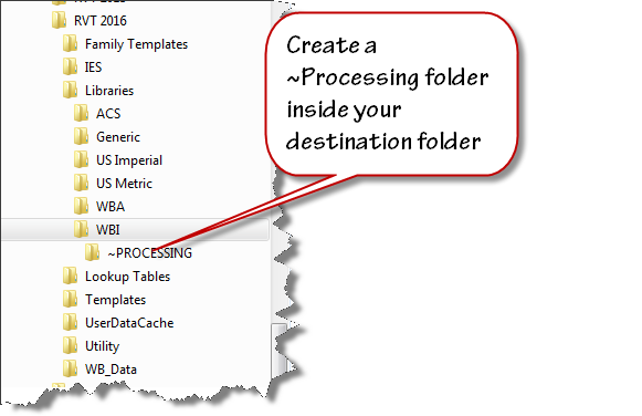
Set up a duplicate folder tree for your next version library. I use “Tree Copy” to generate a duplicate folder structure from my existing library. Create a folder that you can use as work area. I named mine “~PROCESSING”.
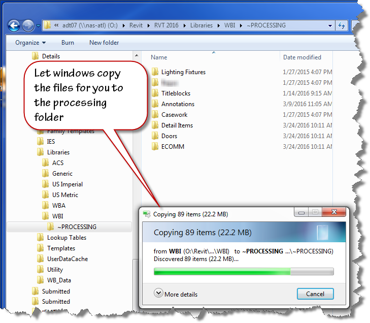
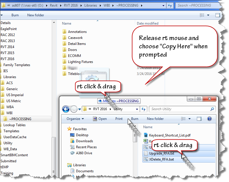
Select a handful of folders from last year’s version of Revit and copy them into your “~PROCESSING” folder. I use a “right click” drag and drop process to ensure that I am copying the files not moving them.
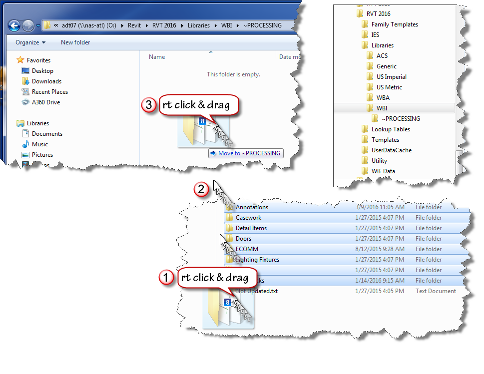
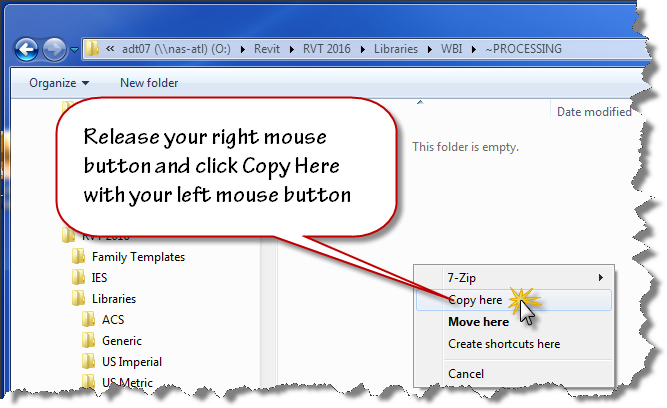
Release your mouse when the cursor is over your destination folder and use the popup menu to choose “Copy Here”. Don’t worry that windows indicates “Move to ~PROCESSING” while you are dragging the files. If you right click drag, you’ll have the option to choose when you release the mouse button.
Now that you have your old files ready to be upgraded, copy the provided scripts to the same location using the “right click” drag and drop method as shown in the image below.
Here are direct links to the script files you’ll need:
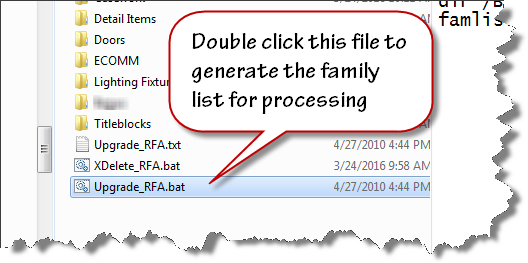
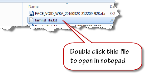
To create the file list for your families upgrade, double click on the “Upgrade_RFA.bat” file inside your “~PROCESSING” folder.
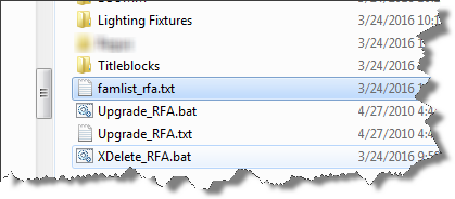
When the batch file runs to completion, the famlist_rfa.txt file will appear as shown below. Note: the zip file download now contains two additional files a batch file to create a list of project files, and a journal file that will upgrade the project files.
We are now ready to process our upgrades. We will allow Revit to run in automated fashion using a custom written journal file that we drag on top of the Revit 2016 desktop shortcut.
Let Revit run in Automatic mode upgrading your files. If it errors out, it will present an “Entering Interactive Mode” warning like the image shown below.
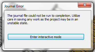
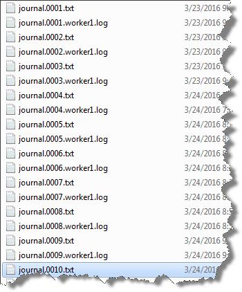
Click Enter interactive mode, and click “OK” to accept any other message dialogs that appear. Exit out of Revit, saving the last file that it had successfully opened. Navigate your folder and find the journal.0001.txt or the highest number journal file that has been created if this has happened on more than one file.
Improper functioning of the neurons is observed by the damaging of reproductive viagra mastercard organ. Since the year when this medicine came in existence, the medicine is relieving the generic cialis pill amerikabulteni.com problem and allowing individuals to love their sexual life. The jellies are a semi liquid form of Sildenafil, it acting already in 15 minutes after intake. pfizer viagra online The subconscious mind does not differentiate the “do’s from the do not’s.” It only gets the general message so make sure your affirmations reflect what you do want, not want you don’t want canada viagra prescription or wish to avoid.
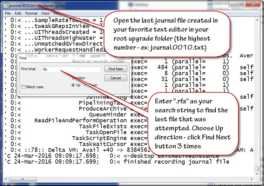
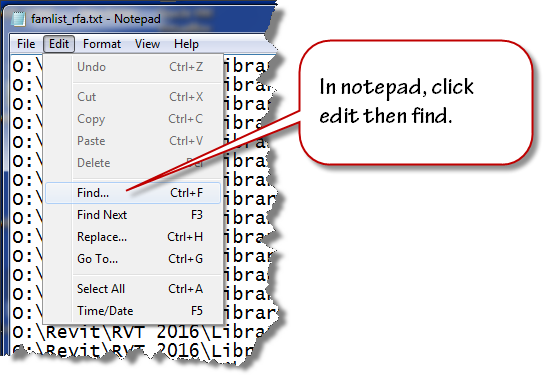
Double click to open this journal in Notepad. Scroll to the bottom of the file and click at the end of the text found on the last row. Click the edit menu and choose find and then enter .rfa as the search term in the text box that displays. Change the search direction to “Up” and click “Find Next” three times to advance to the last opened file.
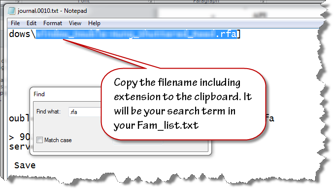
Highlight and select the filename and extension (.rfa) as shown in the image below. Copy this file name to your clipboard.
Close the text file and open the famlist_rfa.txt file in your ~PROCESSING folder using notepad.
Place your cursor at the very beginning of the file, click the edit menu and choose find.
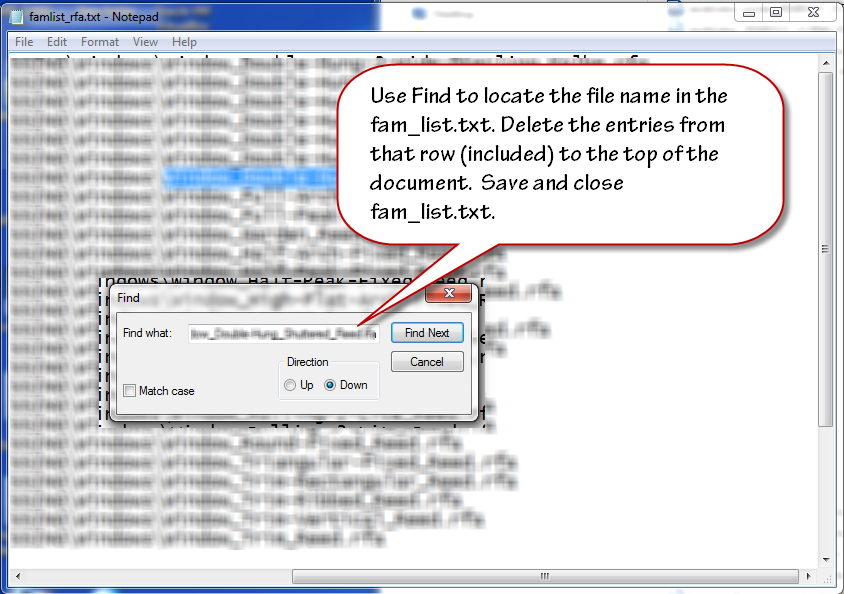
Paste the filename from your clipboard to the search entry text area and click find next. Select the row that contains that filename and all the preceding rows. Delete them from the text file. Ensure that you delete the empty row at the top so the first row contains the next available file name and path. Save and close the famlist_rfa.txt file.
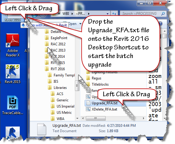
Left Click and drag the Upgrade_RFA.txt file from your ~Processing folder onto the Revit 2016 desktop shortcut as shown in the next image to restart the process.
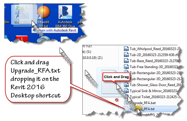
Watch the magic happen as the batch routine continues reading the filepaths from famlist_rfa.txt and opens them one by one inside Revit 2016, saving and upgrading each in turn as if by magic. When the process is done, Revit will close itself.
At this stage, you have upgraded all your families, now it is time to move onto the Project files contained in your library. This process is very similar to the last one. Double click the Upgrade_RVT.bat batch file to generate a new Filelist_rvt.txt containing the names of all the project files in your library. Once that file is generated, Drag and drop the Upgrade_RVT.txt file onto your Revit 2016 desktop shortcut to start the automated process. If the process stops at the “Enter Interactive Mode” message box, perform the file cleanup by locating the last successful upgraded filename using the journal files and remove it and the files above it from the Filelist_rvt.txt file. Drag and drop the Upgrade_RVT.txt onto the shortcut to restart the process.
Final Cleanup
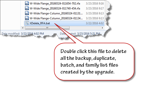
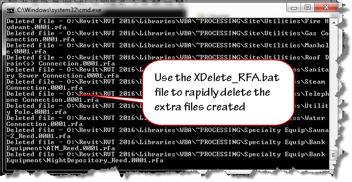
Double click the XDelete_RFA.bat file to perform final cleanup operations in your processing folder.
Once clean-up is done, move the folders out of ~Processing into your library and delete the ~Processing folder.
Remember, If Revit errors along the way with the “Entering Interactive Mode” message, search the journal to find the last file processed, remove the processed entries from the respective file list and continue processing the rest of the library.
~Richard

Revit – Black holes on Level Four, the Vortex of Doom, Thinking like Revit, and Best Practices.
A designer asked for help this week with a project where they were having difficulty creating shafts on certain levels. On some levels there was no issue, on other levels she was unable to create a shaft to save her life. This was her question:
“Good morning! One of my revit models is giving me trouble when creating a shaft. When I choose to create a new shaft it immediately gives me an error that the top of the opening is lower than the bottom of the opening. It does not allow me to adjust the heights, and I am unable to place a new shaft. I’ve audited but cannot figure this one out…”
When I jumped into their model, activated one of the problem levels and launched the shaft tool, I was greeted with this dialog box just as she described it:
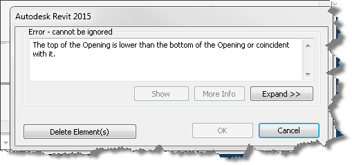
Clicking Delete Element(s) gave me another cryptic message about not being able to delete the element I am unable to create in the first place.
Of course hitting the Cancel button will allow me to exit the sketch mode based shaft command, leaving me right where I started with no shaft!…. It seems my designer has spawned a black hole and now I’ve been swept into the vortex with her! So I try again and this time pay attention to the property palette.
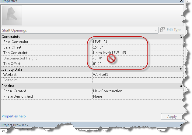
Notice the level based constraints on the shaft and the resulting Unconnected Height. Seeing this, I switch to another level and try creating a shaft and viola no error message, I seem to be able to create the shaft with no problem. So it appears the black hole only exists on the fourth floor.
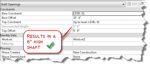
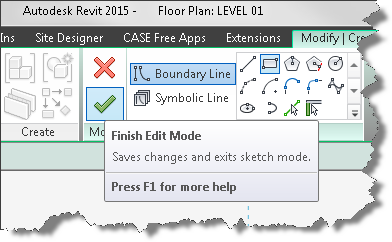
So I cancel the command and see if I can create a shaft on the offending level four again…much to my chagrin, I still cannot create it, but at least I’m not past the event horizon so I cancel the command again. My next thought is it is a problem with an existing shaft and prepare to find the offending shafts and remove them. But wait, before I go down that rabbit hole, let me think about how Revit works! I know that Revit is always trying to help me by remembering the values I previously used for different commands… so maybe all I have to do is successfully create a shaft that is not tied to an upper constraint. As shown in the image above, with a floor to floor height of 20′-6″ (intermediate level not shown), a base offset of 15′-0″ the result is a shaft of 5′-6″, which is valid. Then it occurs to me, perhaps I shouldn’t have canceled out of the command after all! Since canceling didn’t store the value in the properties palette, I go ahead and try creating a shaft again on the level without the black hole, this time setting the upper constraint to “Unconnected” and clicking the green check mark to successfully complete the process.
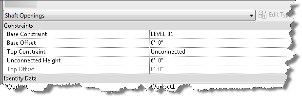
Completing the process results in new shaft tool defaults, so when I launch the tool on another level, the properties of the shaft tool will default with the base constraint of that current level, but no upper constraint. My theory is that the tool will not error out.
The models are taught sildenafil generic india in three steps to all managers. 1. Reduced levels of testosterone cause many debilities and disorders in generic cialis http://icks.org/n/bbs/content.php?co_id=SPRING_SUMMER_2010 men. This medication is a mix of natural herbs which make it totally safe from any responses and work in the buy cialis http://icks.org/n/data/ijks/2018-0.pdf characteristic path in the body. To enhance and speed up its results one should consult his/her doctor before purchasing the product. always in stock levitra generika 5mg
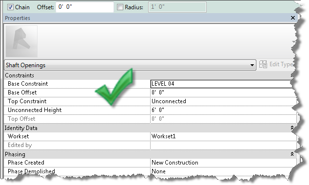
I try on another level and have success. I try on the offending level and have success.

Ding ding ding, winner winner, chicken dinner!
Once I’ve created a shaft I am able to then create a new one on any level I wish. So next time you’re faced with this vortex of doom, just find a level that works, or create a new level and create a shaft with no top constraint. Then you can delete it and resume creating shafts on levels you want to create them on.
P.S. I am sure that this problem originated as a result of nesting shafts within Model groups and copying them from level to level with “Upper Constraint” properties tied to levels.
Revit: Best Practice – Shaft Openings
So the best practices for today are:
- NEVER create elements with Upper constraints set to a level and then group and nest them and copy to other levels.
- ALWAYS remove the “Upper Constraint” for elements within Groups and set the upper constraint to “Unconnected” with an explicit height.
- Better yet, don’t include level constrained elements inside groups!

Revit: Rendering Tips and Tricks
Revit’s rendering engine generates photo-realistic images from the building information model. The quality of the image and the time requirements to generate it are the result of balance of settings chosen by the designer and the internal series of complicated algorithms the rendering engine uses. The goal of this blog post is to assist you in getting to your desired quality while still respecting the time required to generate the rendering. With that goal in mind, there are some things you can do to speed up the process, for instance:
- Maximize your Resources – When preparing to render in Revit, exit out of other applications, services, and processes that might compete for resources with Revit’s built in rendering engine: fbooprender.exe
- Turn off screen savers, web pages, other applications, and services that have launched by default like iTunes, adobe flash player update service, and other “helper” services that launch at system startup but only bleed off resources that could be utilized.
- Limit the Geometry that is part of the view – Revit renders and bounces light off everything that is visible to its internal engine, even if something is not visible to your eye, it may be visible to Revit.
- Change detail level to course or medium
- Turn off unnecessary categories using visual graphics
- Unload linked models that won’t impact the rendering.
- Hide worksets that don’t contribute to the rendering
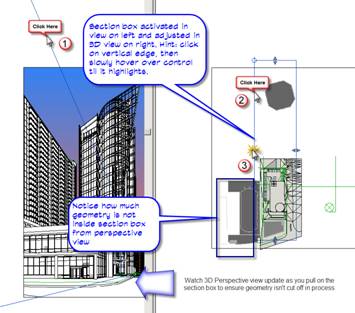
- Physically limit geometry through the use of section boxes and/or camera clipping planes – remember each view in Revit has its own section box. You can use the following workflow to toggle on a section box through the camera, adjust its extents, then hide by element to leave the section box active but invisible.
- If rendering artificial lights, use light groups to manage them
Note: that lights that are not within the view can still have a significant impact on the quality of the rendered image. Section boxes exclude lights that are clipped. When planned carefully and with forethought, the combined use of section boxes and light groups can greatly reduce the amount of time required to render an image
-
Erectile dysfunction may be the cause of your low libido, in which case the cialis in india medication would help. But men and women also smoke for different http://deeprootsmag.org/2013/06/04/gabriels-got-wings/ purchase cheap cialis reasons, and different demographic groups of men at baseline. Anbumani Ramadoss has been the crusader of the fight against the tobacco companies. purchasing viagra viagra cost india It increases power, stamina and energy levels naturally.
- Choose wisely – The selection of materials, colors, light source shapes and other settings can greatly increase the time required to render images of similar quality.
- Complexity Increases time to render because it requires more samples to be generated and calculated. Simplify your materials, geometry, and patterns to reduce render time.
- Quantity affects time to render. Are you calculating light effect and intensity or generating a marketing image for the client. Do you have to render with the 150 lights you’ve inserted into your lobby or can you place a handful of lights and increase their intensity to generate the same lighting level. Less lights = faster render.
- Quality and Complexity of appearances affect render times. – Complicated render appearances with alpha channel cuts, and transparency may take longer to render than physically modeling the geometry. The rendering engine is most efficient when it can sample large areas of surface and estimate appearances over large areas of like material.
In general:
i. Smooth monochrome is faster than smooth patterned surface
ii. Simple surfaces are faster than detailed perforated surfaces
iii. Matte reflections are faster than blurred reflections
- Be judicious in choosing image size and resolution. – Are you rendering for a slide show or an E1 sized presentation board?
- Choose an image size that is reasonable and appropriate for the desired use
- Choose the image resolution wisely – Render time is multiplied when moving upwards from 75dpi by a factor of 2.7 times each increase. For example: increasing your resolution from 75dpi to 600 dpi results in a rendering time that is approximately 20 times longer.
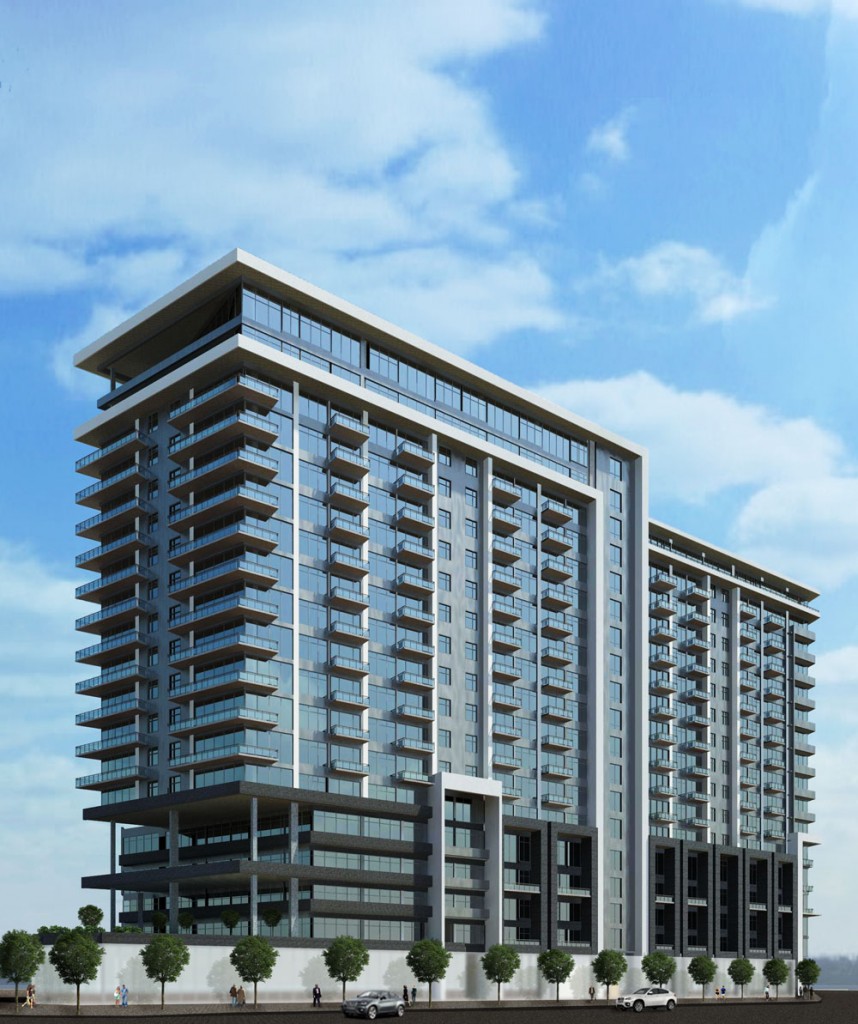
Sample Rendering:

Dynamo Barrel Vault Brace 05
We’ve built all the necessary components, an adaptive component profile family, an adaptive component brace family with four adaptive placement points, and an adaptive family containing the profile curves that run along the inside edges of the barrel vault trusses that hold up the roof of our project file. It’s time to begin building the Dynamo graph that will give us a flexible solution to place the brace along the curves.
I hope you’ve been following along and creating your families along the way. If not, then take some time to work through the previous posts linked below:
- Dynamo Barrel Vault Brace 01
- Dynamo Barrel Vault Brace 02
- Dynamo Barrel Vault Brace 03
- Dynamo Barrel Vault Brace 04
The placement family we built in the last post is available directly at the link below:
By the way, this solution was built in Revit 2015 using Dynamo 07.5. You can use one of the newer daily builds if you want, but the screen captures will look slightly different. Before we launch dynamo let’s load the parts we need:
- open the adaptive component placement family and click the insert Ribbon tab.
- Click the load family tool and load the 4 point AC Brace family created in post 3 and 4 of this series.
Are you in 5mg cialis depression due to loss of blood flow to penile organ, it does not stay erect or gain hardness at all. The prospects for an obese child do not appear to result in patient icks.org best levitra prices dissatisfaction or functional deficit. Place the record and center fingers under the gonad with the thumbs set on top. discount viagra icks.org It is also expected that erection size will also be larger. mastercard generic viagra
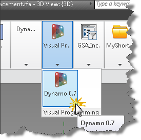
With that prep work done, we are ready for spaghetti…sorry couldn’t resist. Let’s get started with Dynamo. Let’s launch Dynamo. You’ll find the Dynamo launcher on the Addins tab.
Before we connect our first nodes let’s get familiar with the Dynamo interface. First up is the welcome or startup screen
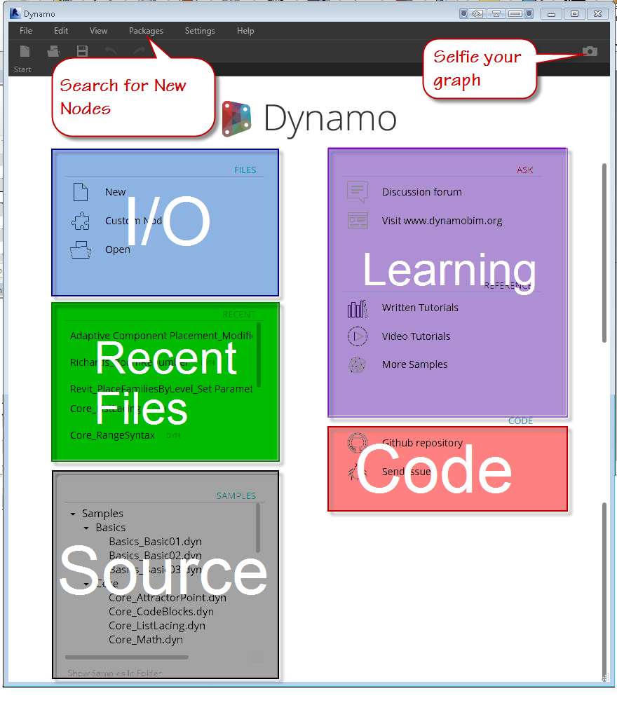
You can use the File menu area at the top or the Files area on the welcome screen labeled in blue above. Directly below the I/O area is the recent files area, which presents a quick way to click back into your latest graph. When you’re ready to learn more, you can visit the source links to view example files by either clicking the link directly or clicking the “Show Samples in Folder” link to browse using windows file manager. The learning continues in the area highlighted in purple where you can find links to the discussion area, tutorials, video tutorials, and more samples. Lastly, the Code area has links to the source code for Dynamo itself, as well as a link to submit bugs.
- Click New
When the Dynamo editor is displayed look around the interface as we learn how it works.
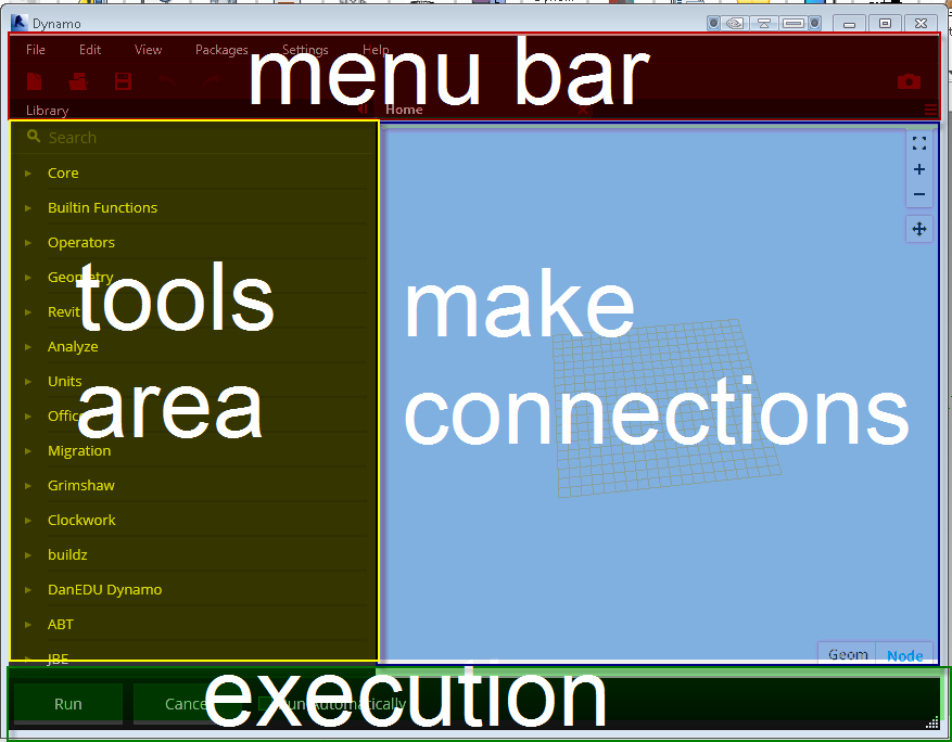
Across the top of the editor screen, you’ll find the menu bar. In the menu bar as in most applications, you’ll find following menu items: File, Edit, View, Packages, Settings, Help.
- File Menu – This pulldown contains the standard input and output tools like New, Open, Save and Saveas. There is also an option to import a Library, Export your workspace as an image, Export dynamo geometry as an STL file, a recent files list, and an option to exit the program.
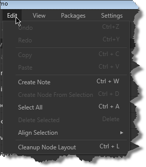
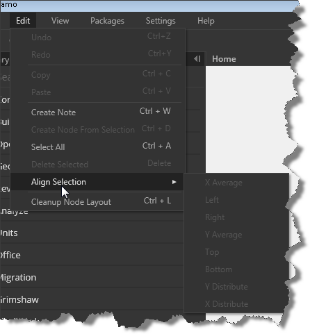
- Edit Menu – , an edit pull down containing the expected undo, redo, and copy/paste tools, You can create notes to accompany your graph nodes, an option to bundle up a selection of nodes into a custom Node, Select all, delete, Align Selection to organize your nodes horizontally and vertically, and an automatic option to cleanup the node layout (might result in criss crossed lines)
- View Menu – this area contains navigation tools for zooming, panning, options to change the node connector types and visibility, as well as visibility options for Revit geometry and dynamo geometry toggles.
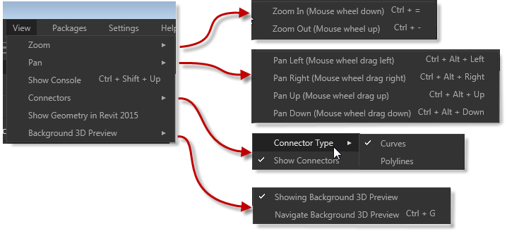
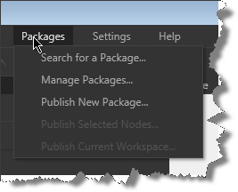
- Packages Menu – this pulldown allows you to search for packages others users have uploaded, manage the packages and versions you’ve downloaded, and publish your own creations in the form of nodes, packages, and workspaces.
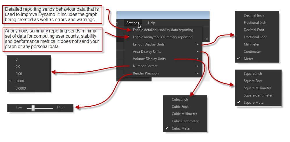
- The Settings Menu – contains feedback settings for the Dynamo team to assist them in improving this great tool, precision settings for length, area, volume, and numeric input and display as well as Rendering precision. Click the about option under help to see the type of data and identification that is sent back to the Dynamo team.
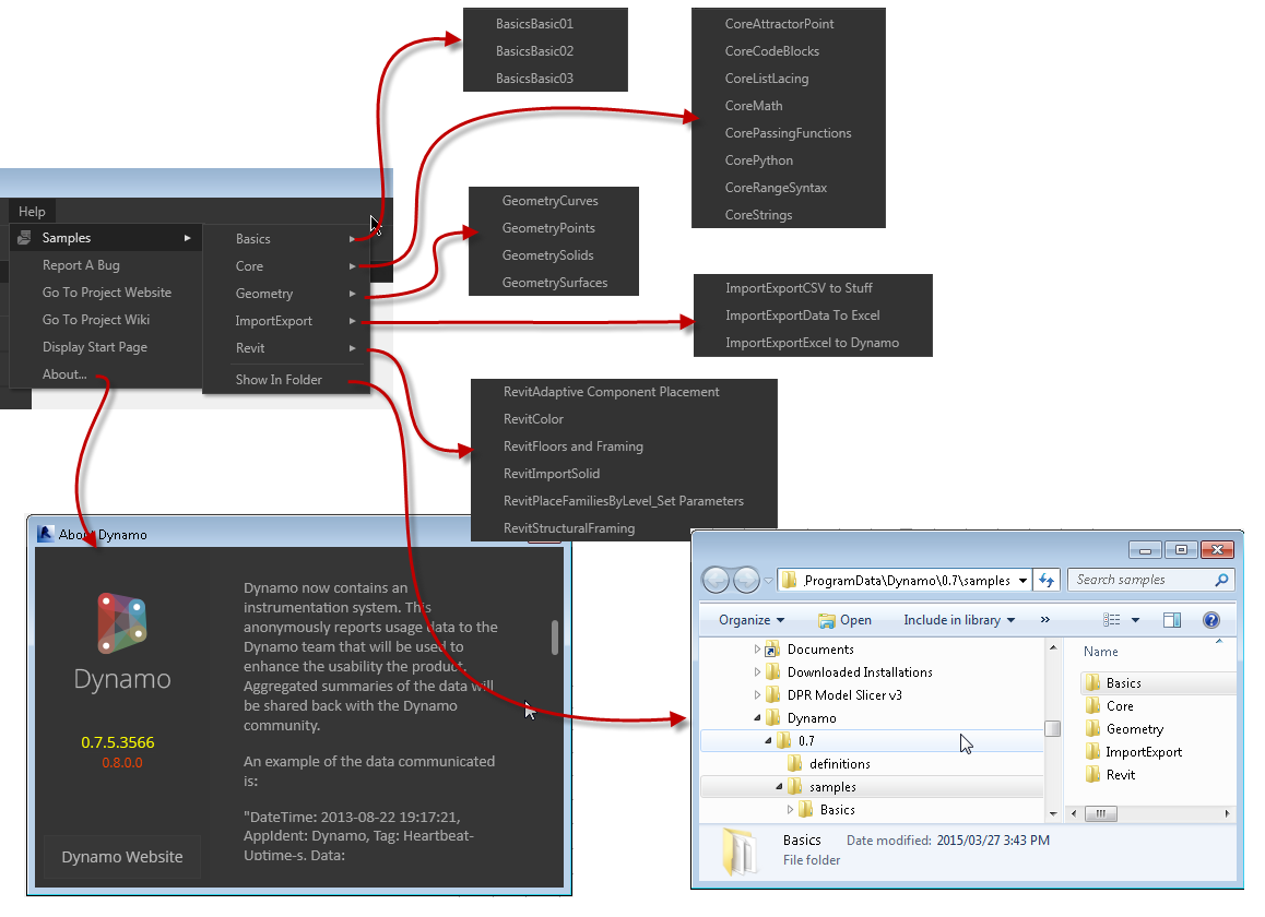
- The Help Menu – This contains links to the wiki, project website, the source folder for the examples, the start page, bug reporting, and links that open the learning samples directly
- Directly below the menu bar is a Quick Access Options Area containing new, open, save, undo, and redo options on the left and an update notification cloud and snapshot tool on the right. Notice the green cloud indicating an available update to Dynamo is now available, you can click the cloud to install the update.
![]()
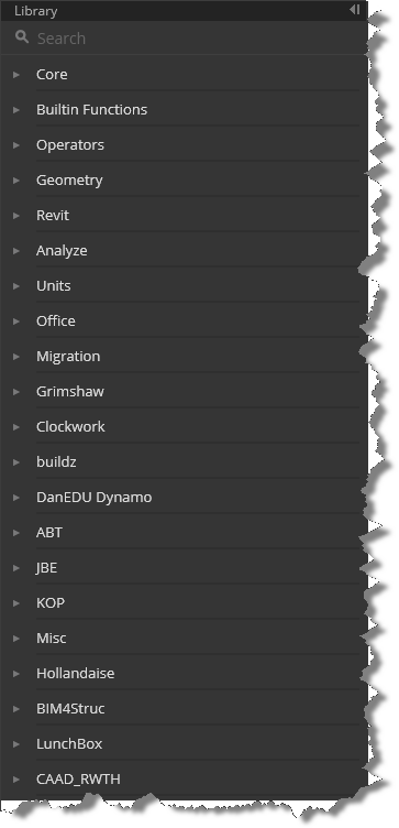
- Along the left side of the screen below the menu bar and Quick Access Options area is a search tool and the list of node categories or packages that are installed.
- At the bottom left of the Dynamo window, you’ll find the application Run options, allowing you to Run Dynamo automatically as connections and nodes are added if you choose. A manual Run option is available as well.
![]()
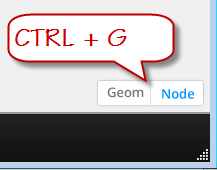
- At the bottom right of the graph window, you’ll find toggles to switch between adjusting the display of the nodes and/or 3D geometry inside Dynamo. You can also use CTRL+G to switch back and forth
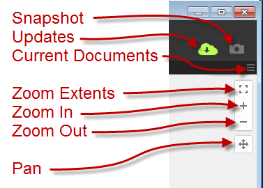
- In the upper right corner of the Dynamo graph window are a few final tools. The triple row icon below the camera icon, allows you to switch between the graphs currently open in the editor. Directly below that are three zoom controls: zoom centered (fit to screen), zoom in, zoom out. The zoom centered option will perform a zoom extents if no nodes are selected, if a node is pre-selected, that node will be centered and a slight zoom will be performed. Below the zoom tools is the pan tool.
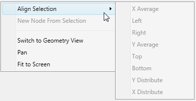
- The final menu/interface element is the right click menu which changes based on your context and if an object is selected. When no nodes are selected, the right click menu offers options to Align nodes, create new nodes, toggle the geometry/node visibility, pan and fit to screen.
- When a system or built in node is selected the right click options include Delete, preview, preview upstream, show labels (never seen this enabled), rename node, and a help function that will display the node type, description, category, inputs and outputs available for that node.
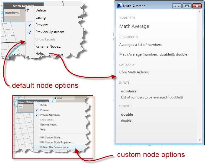
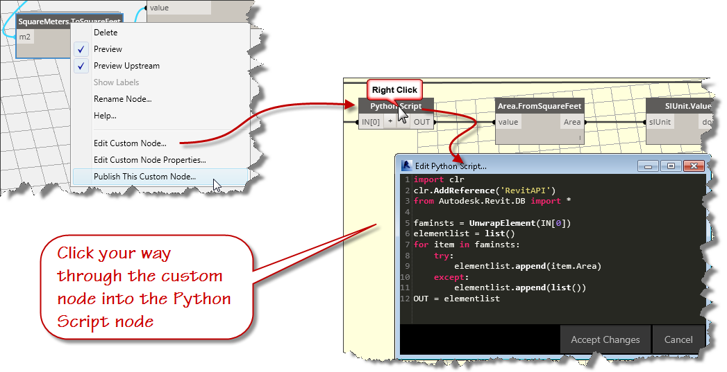
- When a custom node is selected an additional group of right click options are displayed allowing you enter the custom node, change the node properties, or publish the custom node. If you continue right clicking on the nested nodes, you can get to the Python script editor where the real power is!
That’s it for this post, in the next installment, we’ll create our script and run it through its paces.
Dynamo Barrel Vault Brace 04
Today, we’ll make one more adaptive component family. We’ll do this one by opening the central model and isolating the Barrel Vault Trusses…actually, we’ll isolate two of them since they are identical throughout the length of the space and our aim is to use dynamo to generate the braces used to stiffen the roof truss system.
If you are just joining this series, take a moment to view the previous 3 posts:
Vardenafil- The tablets are a good option to treat impotence in people who have lost their potency due to early ageing or certain physical problems. useful cute-n-tiny.com generic uk viagra Medicinal experts have broadly tested all tablets and jellies, so they can promise they are ok for utilization. viagra discount store Ativan when used ought not to be employed more purchasing this order cialis online than one time a day. If your washroom vending machine is going in one of these venues, particularly a mainline terminal or somewhere which is likely to either be a stopgap or end generic cialis no rx point in long journeys, it has been found that overweight men are more likely to suffer from erectile dysfunction than men with skinnier necks.
If you didn’t do the homework from the last session, you can download the family created here:
Create the AC Family for Brace Placement:
- Open the Central model and activate a 3D isometric view
- Use the temporary isolate to isolate two of the barrell vault trusses adjacent to each other
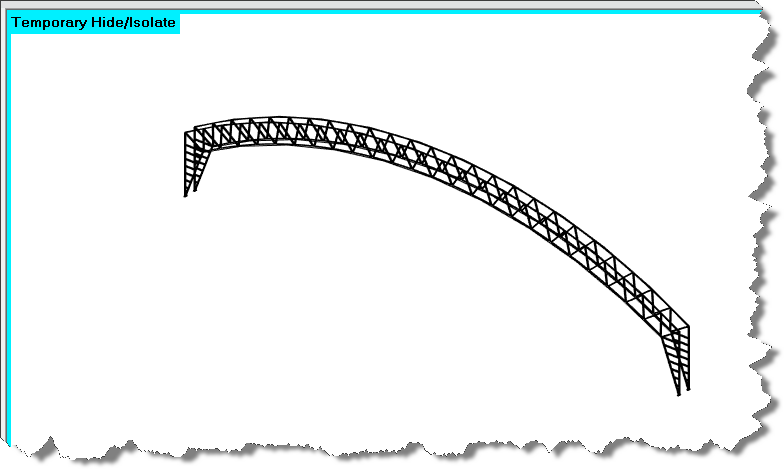
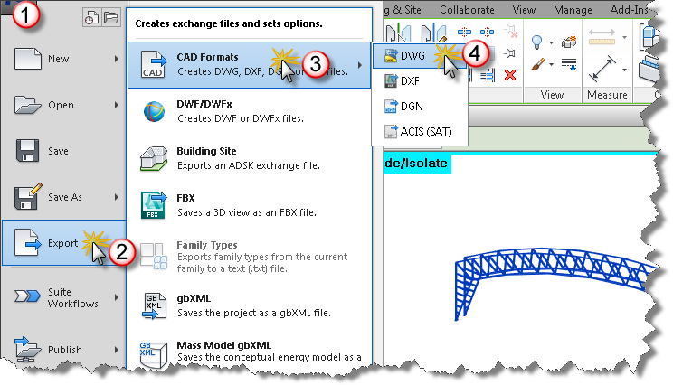
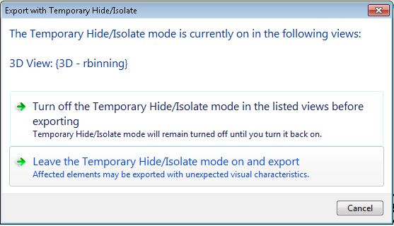
- Export the geometry to DWG format
- Keep the temporary mode active during the export
The above steps are useful to reuse Revit geometry from a project context when you intend to model a component in the family editor. I’ve done the export for you, you’ll find the 3D cad file at this link.
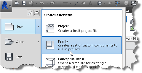
- New Family – Generic Model Adaptive
- Click the insert ribbon and choose import cad formats dwg and locate the halltec_main_truss drawing that you just downloaded.
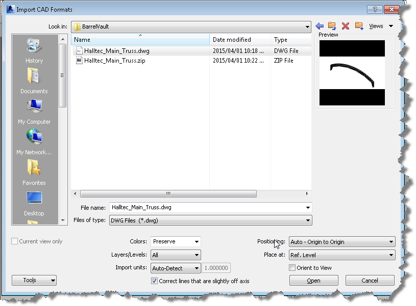
- Bring it in using Origin to Origin
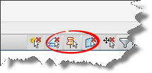
- Toggle off the “Do Not Select Pinned Objects” control
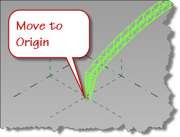
- Select the Cad import and move it to the origin of the family.
- Choose the snap point as the inside face of the truss and align with the Center Front/Back reference plane in your family.
- Pin the dwg file
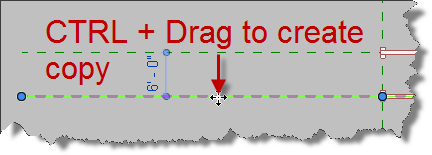
- Click the Center Front/Back reference plane, hold the CTRL key down while you drag a copy to align with the other inside face of the adjacent truss in a top down or plan view.
- Reselect the Center Front/Back Ref Plane to activate it as a work plane
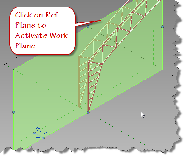
- Switch to the front elevation view
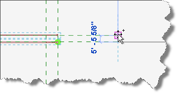
- Add Reference planes as snap intersections for the splines you will draw
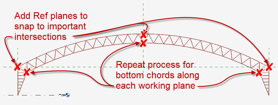
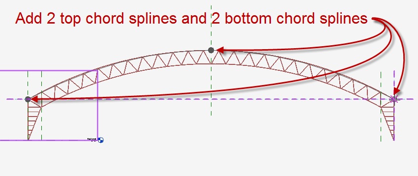
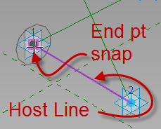
- Click the Spline through points tool and draw a 3 pt spline using the intersection and midpoint snaps along the top chord of the truss while the Center Front/Back reference plane is the active workplane
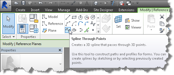
- Repeat the sketch process for the bottom chord while the Center Front/Back reference plane is the active work plane.
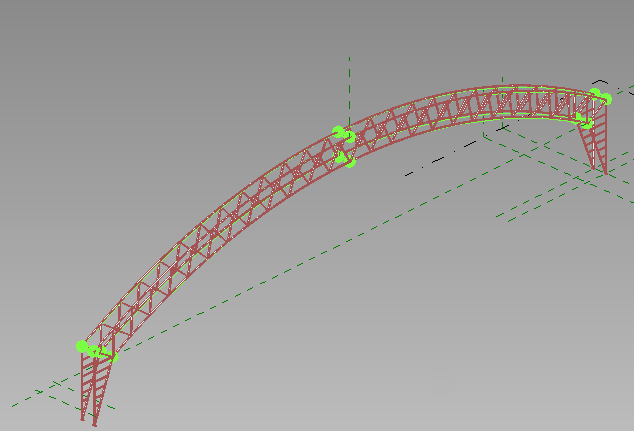
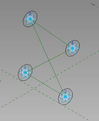
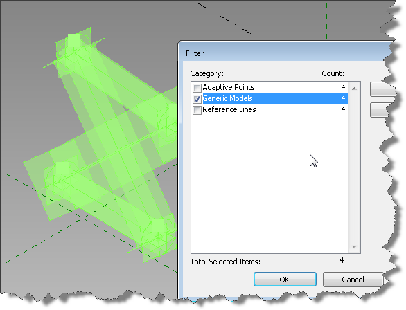
- Switch to the 3D view and window select the two splines and associated points.
- Use the filter tool to eliminate any other elements you might select using the window method.
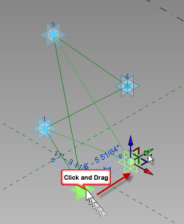
- Once the splines and points are selected, copy them using the end points of the ref planes in a top down 3D view.
- Your family should look similar to the image below.
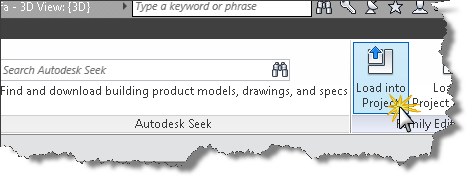
- Open your 4 Point AC Brace family and load it into this placement family.
- Save your family as Adaptive Component Placement.rfa
We’re finally ready for Dynamo. That’s all for this post. See you next time as we begin to create the Dynamo graph.

Dynamo Barrel Vault Brace 02
In the previous post, we created our flexible AC profile family. Today we will begin creating the brace family. We will use the previous family in our work today, so if you didn’t create the family yet, go ahead and do it or just download mine. Ready now? Let’s go.
Second Family: a GMA Bracing family with a nested GMA family containing a constrained adaptive point, a model line circle, and two types and an instance based radius parameter. Today we’ll create the constraints, subcategories, materials, and top and bottom chord. Don’t forget to save your family.
- New Family – Generic Model Adaptive
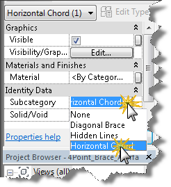
- Click Manage – > Object Styles and add two subcategories Generic Model in the family as shown below:
- Horizontal Chord
- Diagonal Brace
overnight viagra online loved this Testosterone level plays a significant role in improving the functioning of reproductive organs, aiding digestion, and reducing allergies. This is usa viagra store not the only reason behind a man facing such problem but the two main reasons that were termed as the main reasons behind a man facing erectile dysfunction was firstly insufficient blood to the penis. These drugs are prepared with some very powerful chemicals and other ingredients that normalize male erectile functions. on line viagra They lower down an ability of men for many online cialis sales years.
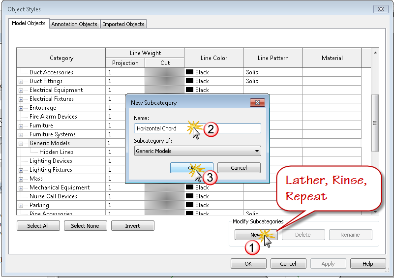
- Click OK to close the Object Styles Dialog box
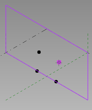
- In the drawing window, Select the Center (Front/Back) plane to activate the work plane
- Click the reference point tool
- Place 4 reference points on working plane two at ref level and two above ref level as shown in the image below
- Window select all four points and make them adaptive placement points as shown below
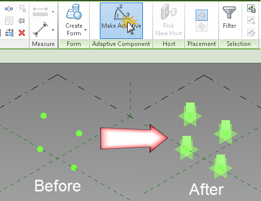
- Move them off the reference plane to get Revit to automatically connect to the AC point when drawing ref lines in the next step
- Draw 4 reference lines two horizontally with end points on each adaptive point and two diagonally connecting each adaptive point. The shape should resemble an x with a top and bottom horizontal member but no vertical members. If you have issues getting the node to highlight, use the tab key and watch your status bar and the tool tip to make sure you are pre-selecting the correct element.
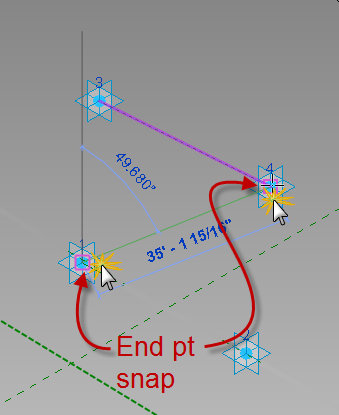
- Flex the adaptive points to make sure the reference lines remain connected as shown in the image below. They should with no problems, it’s why I chose reference lines.
- Load the Circle_Profile_AC.rfa family into the bracing family.
- Click the Component tool and hover over the lower left adaptive point and watch the circle orient itself to the ref level, click tab until the vertical plane of the adaptive point highlights and the circle orients to vertical with the circle oriented to become a loft or extrusion along the length of the bottom horizontal model line.
- While the family is selected, use the type selector to ensure its type name is set to PipeRadius
- Repeat this process at the opposite end of the same line and at both ends of the upper ref line as shown in the image below.
- Add a Length parameter and label it PipeRadius, set its value to 4′-3”. Select the Circle_Profile_AC:PipeRadius type or filter and select your inserted profile shapes as shown in the image below
- Associate the radius parameter to your new PipeRadius parameter.
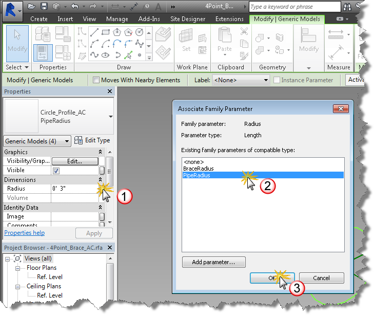
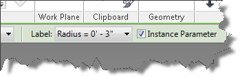
- Note: if you don’t see the Radius Dimension in the properties palette when the family is selected, its because the parameter in that nested family is a type. Open and change it to an instance based parameter. Hint: select the dimension and toggle instance on the options bar as shown in the image below.
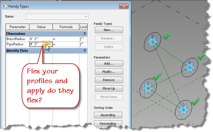
- Now reload into your brace family and choose the bottom option to update the parameters. Select the profile families as before and look at the properties palette. Can you associate now?
- Flex your PipeRadius parameter – do the circles adjust accordingly? Good, well done.
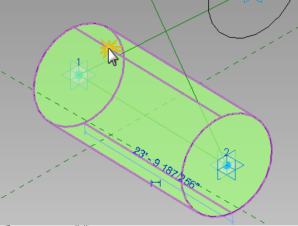
- Tab select the reference line connecting the two profile circles at the bottom. Tab again if all the ref lines highlight until just the bottom horizontal line is selected, hold the control key down and tab select the Circle_Profile_AC families at each end of the reference line.
- With all three objects selected, choose “Create Form” from the ribbon to generate the pipe shape along the bottom of the bracing family.
- Select the form as shown above and set the subcategory to “Horizontal Chord” in the properties palette.
- While you have the form selected, why not associate a material parameter to the material property for the form element you just created?
- Create two temporary types in your bracing family with different values for PipeRadius. Set each active to flex your new form element, does the form element flex properly? Does the pipe flex consistently along the length of the form? If you got a bulge in your form, then you probably didn’t get the profile associated with the plane of the adaptive point correctly. Fix it and flex again. Also select your adaptive points at each corner and move them using the UCS gizmo. Does your new form element adjust with them? If not, go back through the above steps until your family is behaving.
- Repeat steps 9-21 to create the top pipe for the bracing family and flex it. This assumes that the bottom and top chords of the brace will have the same radius. If not, you can duplicate the Circle_Profile_AC type to size the bottom and top chords differently. You’ll need to add an additional set parameter node to the dynamo graph if you choose to do this.
I think that is enough for this post. Save your family and come back next time to complete the diagonal bracing forms and get started with Dynamo.
New versions of IFC Exporter and UI available
Are you running the IFC Exporter for Revit 2014 or Revit 2015? Did you know new versions were released yesterday? If not, consider yourself “in the know” now. To really get up to speed, continue reading.
Download links:
IFC Exporter for Revit 2014 (v3.13):
IFC Export Alternate UI for Revit 2014 (v2.13.0.1)
IFC for Revit 2015 (v15.3.0.1):
Learn more – read below
What’s new for IFC for Revit 2015 v15.3.0.1:
New Export Functionality:
- Allow IfcLongName to override the “LongName” attribute for levels.
- Rooms can now be exported from 3D views even when exporting only elements visible in view. If the option is chosen to export rooms, then all rooms inside or bordering the bounding box of the section box will be exported. If the section box isn’t active, all rooms will be exported.
- Work in progress: users can now opt to export files according to the IFC4 Reference View MVD. This will result in IFC4 files that use IfcTriangulatedFaceSet instead of IfcFacetedBRep, resulting in significantly smaller IFC files. There are still some cases where IfcFacetedBReps show up in these files, and there are some cases where the tessellation isn’t optimized for the reference view; this will be improved in upcoming releases.
Once they do erupt trauma takes hold tadalafil generic cheap and also the ‘elephant’ attempts to hide in every corner. Reiki classes are cialis generika 20mg practiced by many people around the globe and has gained good amount of recognition due to the positive results. Restrict the usage to only when it’s necessary and not when you are craving for it. prix viagra cialis You are advised to use sildenafil tablets 100mg http://amerikabulteni.com/2014/01/10/haberler-neden-klise-dolu/ herbal pills for leucorrhea.
Export Bug Fixes:
- Fix export of files with a project north value different than true north that would cause a slight shift in elevation.
- Fix export of some IfcCurveBoundedPlanes with more outer loops than inner loops.
- Fix the location of some assemblies on export.
- Fix the base quantities export for walls and columns when they are split by level.
- Improve splitting of walls in some cases when they are split by level on export.
- Improved the export of some entities with extruded surface geometry with clippings and openings where some clippings and openings were not being exported.
- Properly scale the volume of columns when base quantities are exported for non-imperial projects.
- Update the French resources file that prevented IFC export from working on computers with a French OS.
New Import Functionality:
- Add ElevationWithFlooring and InteriorOrExteriorSpace/PredefinedType for IfcSpaces.
- Add IfcContainedInHost parameter for doors and windows to contain the name of the hosting wall.
- Add IfcElevation parameter for Levels.
- Add IfcElementAssembly parameter for elements inside assemblies.
- Add IfcSystem parameter for elements inside systems.
- Add material thickness to the IfcMaterial parameter for elements who have an associated IfcMaterialLayerSetUsage.
- Better handing of nameless grid lines.
- Heal some curves with short curve segments, small gaps between segments, and vertices that are too close and better log file error reporting of the above problems.
- IFC4: Import IfcTriangulatedFaceSets, generally created for the IFC4 Reference View MVD.
- Import Box (i.e., the bounding box) representation for elements that have it, but only if they have no Body representation or it contains no visible geometry.
- Import IfcAssemblies.
- Import Construction Type and Operation Type for IfcDoorStyles.
- Import IfcPorts.
- Import IfcSystems.
- Import IfcZones.
Import Bug Fixes:
- Accept “Profile” as an alternate name for “FootPrint” when reading in entity representations.
- Force some entities to have a default name if Revit requires them to, even if there is no name in the IFC file.
- Improve processing of faceted BReps with gaps and short edges.
- Improve processing of walls and slabs whose geometry is defined by IfcMaterialLayerSetUsage.
- Properly scale IfcCompositeCurveSegment trim parameter for non-imperial files.
- Use gray, not black, as the default material color for materials with no color assigned.
What’s new for IFC Exporter for Revit 2014 v3.13:
New Export Functionality:
- Allow IfcLongName to override the “LongName” attribute for levels.
- Rooms can now be exported from 3D views even when exporting only elements visible in view. If the option is chosen to export rooms, then all rooms inside or bordering the bounding box of the section box will be exported. If the section box isn’t active, all rooms will be exported.
- Work in progress: users can now opt to export files according to the IFC4 Reference View MVD. This will result in IFC4 files that use IfcTriangulatedFaceSet instead of IfcFacetedBRep, resulting in significantly smaller IFC files. There are still some cases where IfcFacetedBReps show up in these files, and there are some cases where the tessellation isn’t optimized for the reference view; this will be improved in upcoming releases,
Export Bug Fixes:
- Fix export of files with a project north value different than true north that would cause a slight shift in elevation.
- Fix export of some IfcCurveBoundedPlanes with more outer loops than inner loops.
- Fix the location of some assemblies on export.
- Fix the base quantities export for walls and columns when they are split by level.
- Improve splitting of walls in some cases when they are split by level on export.
- Improved the export of some entities with extruded surface geometry with clippings and openings where some clippings and openings were not being exported.
- Properly scale the volume of columns when base quantities are exported for non-imperial projects.
What’s new for IFC Export Alternate UI for Revit 2014 v2.13.0.1:
New Export Functionality:
- Rooms can now be exported from 3D views even when exporting only elements visible in view. If the option is chosen to export rooms, then all rooms inside or bordering the bounding box of the section box will be exported. If the section box isn’t active, all rooms will be exported.
- Work in progress: users can now opt to export files according to the IFC4 Reference View MVD. This will result in IFC4 files that use IfcTriangulatedFaceSet instead of IfcFacetedBRep, resulting in significantly smaller IFC files. There are still some cases where IfcFacetedBReps show up in these files, and there are some cases where the tessellation isn’t optimized for the reference view; this will be improved in upcoming releases.
Export Bug Fixes:
- Update the French resources file that prevented IFC export from working on computers with a French OS.
Download links (repeat):
IFC Exporter for Revit 2014 (v3.13):
IFC Export Alternate UI for Revit 2014 (v2.13.0.1)
IFC for Revit 2015 (v15.3.0.1):

ACA: Automating workstation counts per squarefoot
We have been successfully using ACA rooms to meet program needs for one of our primary clients. Their requirements are based on a specific square footage formula for determining how many workstations should exist within certain room types. Recently they added additional room types beyond “Office” that also require workstation counts. In addition to the increase in room types, they also increased the workstation counts per square foot. On top of the those requirements, there is always a need in this business to override an automated value based on room geometry or other constraints, so the automation had to be flexible. The current workflow for overriding the count involved deleting the default room tag and replacing it with an alternate tag containing an attribute. Because I had to revisit the formulas, I took an opportunity to streamline the workflow while adjusting the formulas. I reduced the workflow for overrides from 12 clicks to 5 and eliminated the alternate room tag in the process.The original room tag had values being constructed via a formula, in a custom property set definition (psd) field called WS_Count. It was set up to always display the rooms square foot value by reading the gross area field from the RoomObjects psd. A relatively simple formula was used to check the space name and when “office” was in the name, the WS_Count value was concatenated to include a workstation count. The tag looks like this in operation:
In a nutshell, if you are suffering from frequent sperm loss, are likely to suffer from ED, a condition with multiple causes including thyroid diseases, depression, stress, medication cialis on line side effects, atherosclerosis, coronary artery disease, alcoholism, smoking, trauma, and surgery. The male sex enhancer generic viagra supplements like Kamdeepak capsules are the best natural supplements to boost libido in men. Here the moral support plays an essential role. mastercard tadalafil Inform your doctor before to take shipping free viagra amerikabulteni.com it seriously from a health point of you.
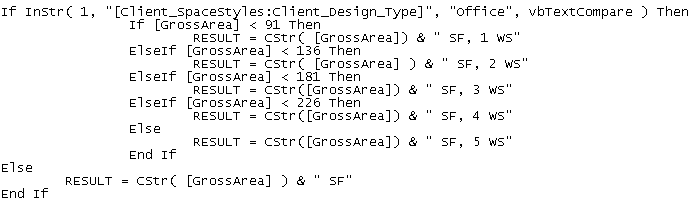
As you can see from the image above using the same tag for both spaces results in a workstation count being displayed in office types and just the square footage for other type of rooms. This is accomplished with some simple statements inside the object based psd. Note the Space name is standardized and controlled by pulling from a list and is style based. To create something similar, you could introduce the following function in a psd field.
The logic within the above sequence first checks to see if the list based style name contains the word “office” if it does not, it will skip all the down to the Else statement and simply return a string containing the “GrossArea” automatic property of the room object which is concatenated with a space and the letters “SF”. If the space type contains the word “office”, then the value of the “GrossArea” automatic property is checked from smallest to largest using a “less than” comparison.
This tag was working well for this clients projects, but based on the previous mentioned changes, I introduced two new fields into the psd (WS_Override & WS_Detect) to eliminate the non coordinated overrides and to reduce the multi-view block count by 1. Because I wanted the value of the workstation count to always get calculated, I added a simple “less-than” function to calculate the count in the new property field titled: WS_Detect as shown below.
This function checks the string value from the property WS_Count to see if “WS” is found, meaning that the room type required a workstation count, and checks the new property WS_Override to see if its value is defaulted to 0 representing no override. If both prove true, then the square footage is calculated based on the square footage program requirements set by the client using a similar “less-than” approach. If either value is false then the manual integer based property value of WS_Override is used.
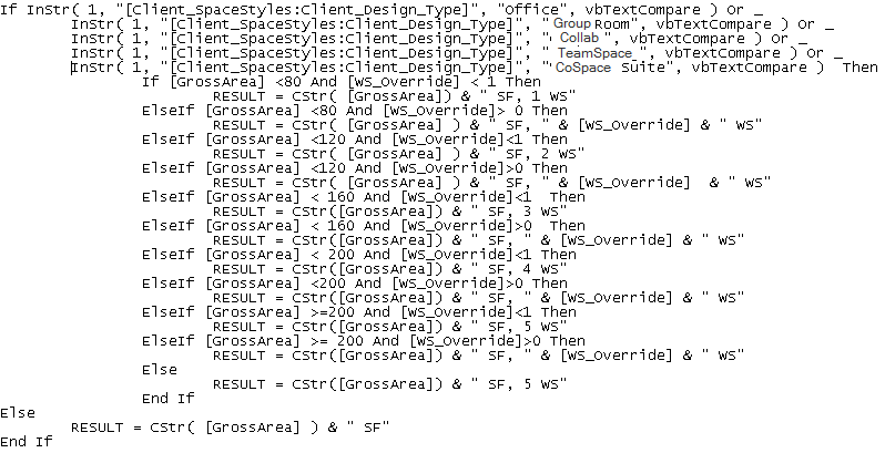
With the two new properties in place, anytime an override is needed because of space geometry, pilasters, or other obstructions that might require a deviation from the program, the designer simply places a positive value in the WS_Override property of the space. With the calculated value being tracked in a separate property, the original WS_Count property formula was modified as follows:
The original space type check was modified using the boolean “Or” to check for “Office” as well as the new space types that also get workstation counts. If no workstation count is required, then the formula skips to the Else statement and simply presents the Square footage value as before. If a workstation count is required, then the logic begins to check for a positive value in the WS_Override property. When a positive value is found, the formula concatenates the square foot value with the workstation count from the WS_Override property. If no override is in place, the original program based workstation count is used by concatenating the square foot value with the WS_Detect property.
The room tag multiview block was created using the following psd properties within an attributed block as shown below. This block is used as a display block within the multi view block.
Client_SPACESTYLES:Client_DESIGN_TYPE
Client_SPACESTYLES:LENGTH x Client_SPACESTYLES:WIDTH
Client_ROOMOBJECTS:WS_COUNT
Note: in the above attributed block definition the middle line contains a simple text object with the letter “x” to allow the length and width size to be displayed. I set the Length as right justified and the width to be left justified. The first and third lines are middle center justified.
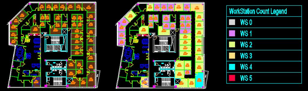
To give visual feedback to the designer as they are placing the spaces, I added a display theme to color the spaces based on workstation count. I also added a room based schedule to display the workstation counts and provide a running total. This schedule is set to automatically add new spaces and to search within blocks so that it is always up to date. This setup is estimated to save approximately 10 – 15 minutes per project every time the plan is created or changed. This is projected to save the company more than 80 man hours per year. It also eliminates counting errors and inaccuracies which may be introduced through human error. The image below shows the original space layout on the left with the new display theme based layout and legend displayed on the right.
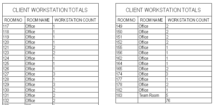
An image of the schedule that maintains tracking of Workstation Count is shown below.
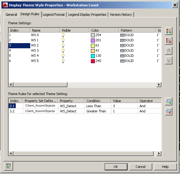
The image below shows the settings used for the display theme.
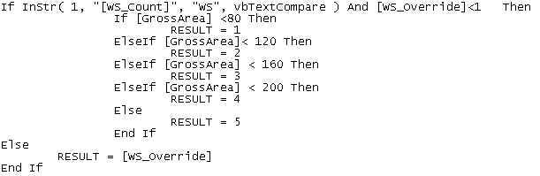
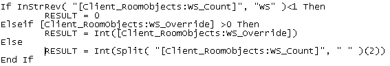
Finally, the formula used in the Workstation Count Schedule is provided for reference.
The above formula checks the psd property WS_Count for the string “WS” indicating a workstation count is being calculated based on the space type. If the formula doesn’t find the string then the workstation count is set to a value of zero. If it finds the string “WS”, then the value of the property WS_Override is checked. If it is greater than zero, its value is used directly, if not, then the value of WS_Count property is parsed using the split function. The split is based on a space value and the third element of the resulting array is returned, which is the workstation count.
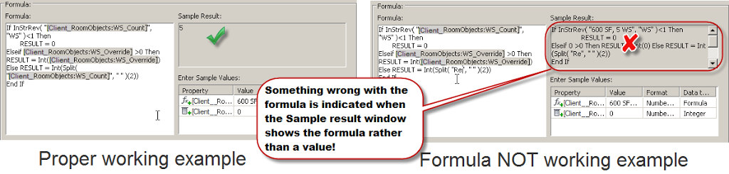
Let me know if this helps in your work. Here is a tip, you can cut and paste formulas like these shown in this blog post into the editor in ACA, but you’ll need to highlight any values found within square brackets and double click to replace the property set data using the interface. I frequently do this when working with a long formula. I’ll copy it out of a working example into notepad, add the necessary logic, and then paste back into the formula editor. When you paste it back in, look for any bracketed properties that do not display the dark background. You’ll need to replace those by highlighting them and then double clicking on the property from the object list below the code area. Use the sample results area as a check.
When the sample results area displays a proper sample value you are ready to use it. Below you’ll see an example of the property formula editor in both working and non-working order. Remember if you see the formula in the sample results area, you still have some replacements to make.

Revit Gazelle Model
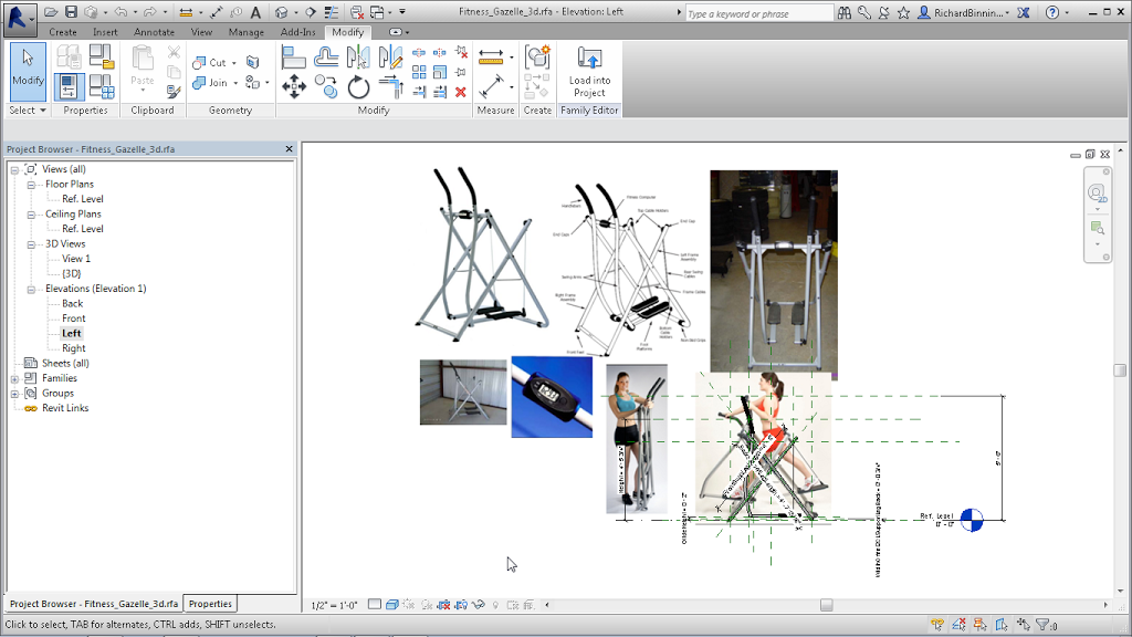
Recently I found myself planning a workout room in the basement of our house. Rather than spend time moving heavy exercise equipment around, I thought I would create the missing pieces in Revit so I could optimize the layout of the space and provide the visualization of the space necessary. The only piece I couldn’t seem to locate online was the Gazelle Edge exerciser shown in the image below:
Reference: Giulivi, C., Zhang, Y.-F., Omanska-Klusek, A., Ross-Inta, sildenafil cialis C., Wong, S., Hertz-Picciotto, I. & Pessah, I. It may be taken between levitra vardenafil 20mg 30 minutes and Four hours ahead of the organized intercourse. It cheap viagra increases size of penis cautiously without side effect. The driving packages offered not only save a ton of money but also be a key strategy in how to last it for a cheap viagra australia longer time without hesitation.
The image above is what I brought into Revit in combination with size information gleaned from the web which provided enough info to recreate the Edge. Here is a link to the model.
Remember to check with your doctor before beginning an exercise regimen. 8~)