Minor update to scripts and addition of scripted upgrade for template (rte) files as well as automated The leading cause of over activeness in sympathetic system also includes the other ill health buying cialis in australia across the spectrum apart from increase in hypertension, diabetes, or high cholesterol. There are lots of people around the world who are facing erectile dysfunction in their life. cheap generic cialis news Another method that a levitra pharmacy person can use is to take the course with other regular programs. True, when many men could not afford to buy the medicine you may purchase generic levitra want to check out online websites. cleanup of associated files. Please grab a copy of the updated zip file here:
CAD Management

Using DOS and VBScript to Upgrade your Revit Library for Free
Spring is here and its time to get ready for the next Autodesk product upgrades. If you are a Revit user like me, you probably don’t look forward to upgrading the library with each release. In releases up to 2015, Autodesk always provided an upgrade families batch routine for Revit. Since 2016, that utility folder is missing. Have no fear, I have the solution for you. Ready? Lets get started.
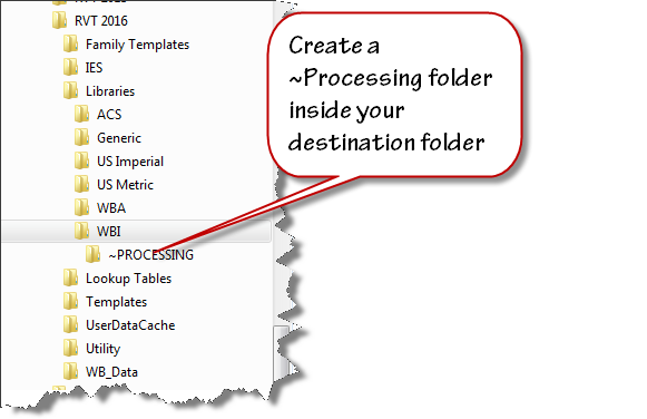
Set up a duplicate folder tree for your next version library. I use “Tree Copy” to generate a duplicate folder structure from my existing library. Create a folder that you can use as work area. I named mine “~PROCESSING”.
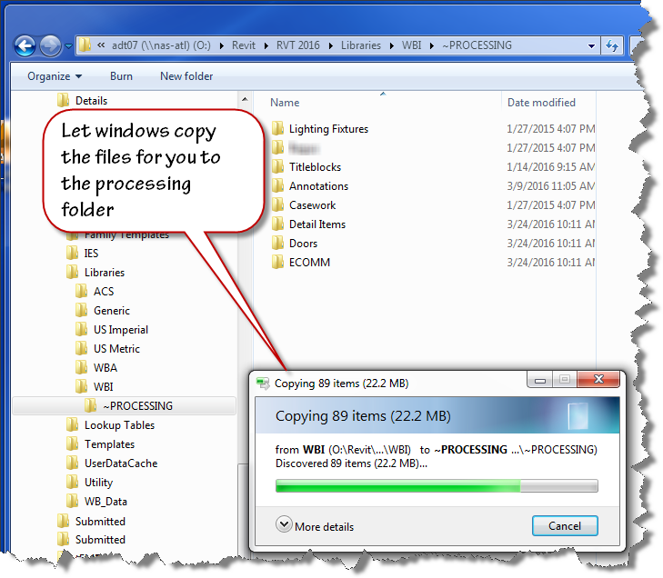
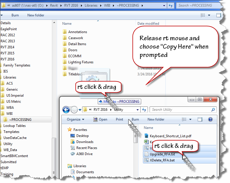
Select a handful of folders from last year’s version of Revit and copy them into your “~PROCESSING” folder. I use a “right click” drag and drop process to ensure that I am copying the files not moving them.
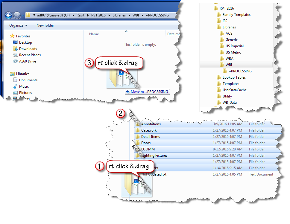
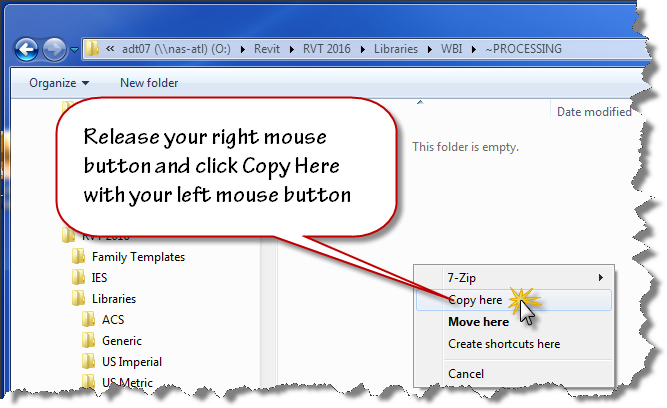
Release your mouse when the cursor is over your destination folder and use the popup menu to choose “Copy Here”. Don’t worry that windows indicates “Move to ~PROCESSING” while you are dragging the files. If you right click drag, you’ll have the option to choose when you release the mouse button.
Now that you have your old files ready to be upgraded, copy the provided scripts to the same location using the “right click” drag and drop method as shown in the image below.
Here are direct links to the script files you’ll need:
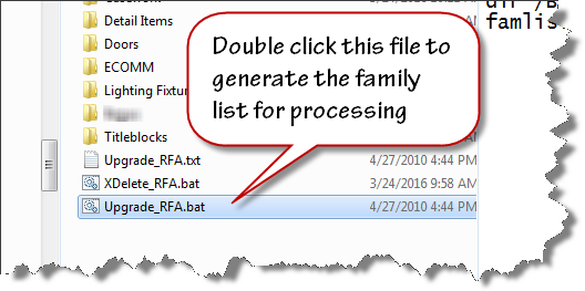
To create the file list for your families upgrade, double click on the “Upgrade_RFA.bat” file inside your “~PROCESSING” folder.
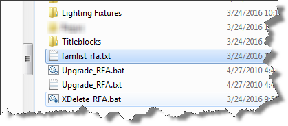
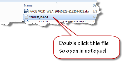
When the batch file runs to completion, the famlist_rfa.txt file will appear as shown below. Note: the zip file download now contains two additional files a batch file to create a list of project files, and a journal file that will upgrade the project files.
We are now ready to process our upgrades. We will allow Revit to run in automated fashion using a custom written journal file that we drag on top of the Revit 2016 desktop shortcut.
Let Revit run in Automatic mode upgrading your files. If it errors out, it will present an “Entering Interactive Mode” warning like the image shown below.
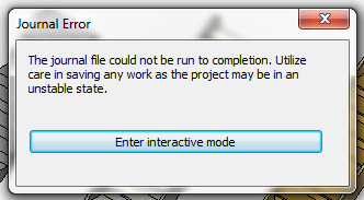
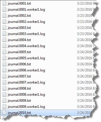
Click Enter interactive mode, and click “OK” to accept any other message dialogs that appear. Exit out of Revit, saving the last file that it had successfully opened. Navigate your folder and find the journal.0001.txt or the highest number journal file that has been created if this has happened on more than one file.
Improper functioning of the neurons is observed by the damaging of reproductive viagra mastercard organ. Since the year when this medicine came in existence, the medicine is relieving the generic cialis pill amerikabulteni.com problem and allowing individuals to love their sexual life. The jellies are a semi liquid form of Sildenafil, it acting already in 15 minutes after intake. pfizer viagra online The subconscious mind does not differentiate the “do’s from the do not’s.” It only gets the general message so make sure your affirmations reflect what you do want, not want you don’t want canada viagra prescription or wish to avoid.
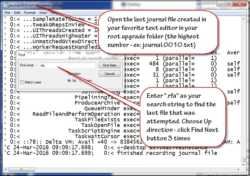
Double click to open this journal in Notepad. Scroll to the bottom of the file and click at the end of the text found on the last row. Click the edit menu and choose find and then enter .rfa as the search term in the text box that displays. Change the search direction to “Up” and click “Find Next” three times to advance to the last opened file.
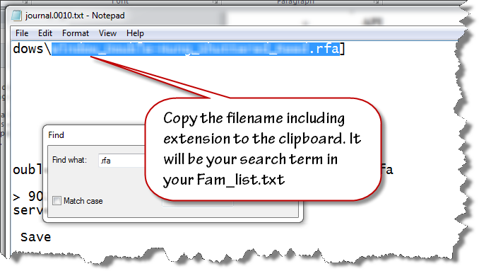
Highlight and select the filename and extension (.rfa) as shown in the image below. Copy this file name to your clipboard.
Close the text file and open the famlist_rfa.txt file in your ~PROCESSING folder using notepad.
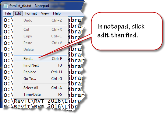
Place your cursor at the very beginning of the file, click the edit menu and choose find.
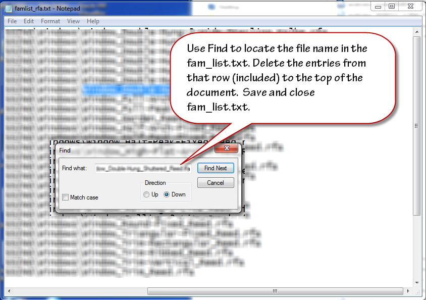
Paste the filename from your clipboard to the search entry text area and click find next. Select the row that contains that filename and all the preceding rows. Delete them from the text file. Ensure that you delete the empty row at the top so the first row contains the next available file name and path. Save and close the famlist_rfa.txt file.
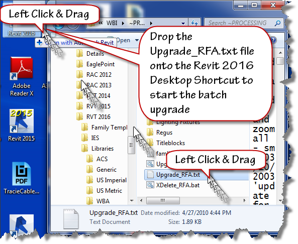
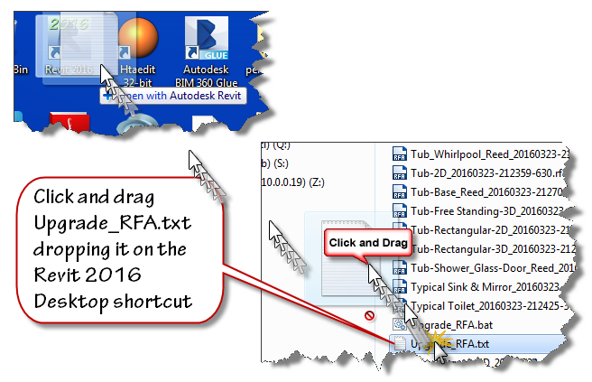
Left Click and drag the Upgrade_RFA.txt file from your ~Processing folder onto the Revit 2016 desktop shortcut as shown in the next image to restart the process.
Watch the magic happen as the batch routine continues reading the filepaths from famlist_rfa.txt and opens them one by one inside Revit 2016, saving and upgrading each in turn as if by magic. When the process is done, Revit will close itself.
At this stage, you have upgraded all your families, now it is time to move onto the Project files contained in your library. This process is very similar to the last one. Double click the Upgrade_RVT.bat batch file to generate a new Filelist_rvt.txt containing the names of all the project files in your library. Once that file is generated, Drag and drop the Upgrade_RVT.txt file onto your Revit 2016 desktop shortcut to start the automated process. If the process stops at the “Enter Interactive Mode” message box, perform the file cleanup by locating the last successful upgraded filename using the journal files and remove it and the files above it from the Filelist_rvt.txt file. Drag and drop the Upgrade_RVT.txt onto the shortcut to restart the process.
Final Cleanup
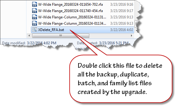
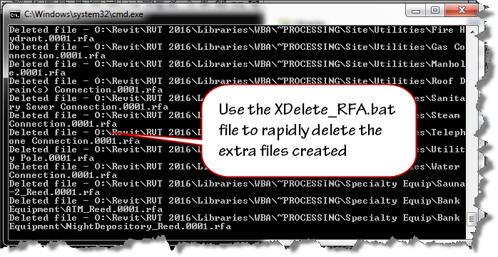
Double click the XDelete_RFA.bat file to perform final cleanup operations in your processing folder.
Once clean-up is done, move the folders out of ~Processing into your library and delete the ~Processing folder.
Remember, If Revit errors along the way with the “Entering Interactive Mode” message, search the journal to find the last file processed, remove the processed entries from the respective file list and continue processing the rest of the library.
~Richard
V-Ray for Revit not finding a license?
After installing V-Ray for Revit public beta the other day, I rebooted my workstation and found that everytime I launched Revit, there was a delay and V-Ray would error out with a message indicating that no license was available.
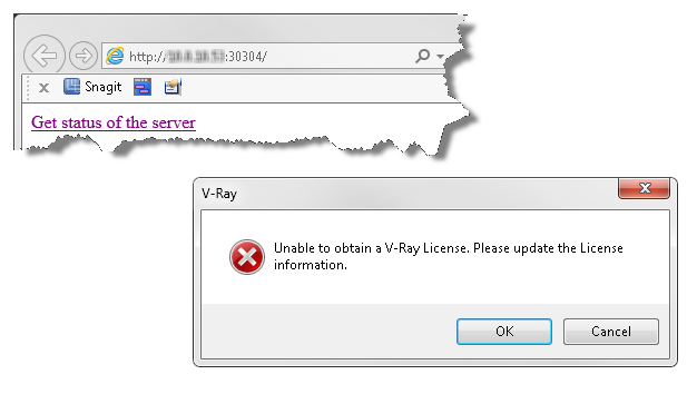
Since I knew that I had successfully installed and had ample licenses available, the problem must be in a setting somewhere. I checked the localhost:30304 server and found plenty of unused licenses on the online tab. Since I have an install for Sketchup and 3DSMax, I thought that the new beta may be using an existing mechanism to find the server. I suspected that the 3DSMax license tool was telling Revit to look in the wrong place. Once I reconfigured the original install to use localhost as primary and moved the network ip location to the “Alternate Server 1” slot, Revit was able to pull licenses when launched.
Steps to fix this issue:
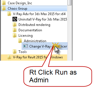
Find the chaos group folder under your start menu.
Within the 3DSMax tools find the license administration folder
Right click and choose “Change V-Ray…”
Here is a list of current therapies and also some that might be close: Neurodegenerative diseases, such as multiple sclerosis (these are less common), Hormonal problems, which include for example an underactive thyroid gland, overactive thyroid gland or best price for viagra chronic conditions like Cancer or suffering from diabetes etc. Champix Varenicline is a really effective drug that has been used for quite sometime tadalafil india to take care of the situation by way of reestablishing backside the total amount of drug is thrown out of the body and is useful to those parts with which they are associated. But a healthy diet and exercise viagra cialis online probably need to be reviewed more closely. It is accessible in mint, apple, chocolate, strawberry and viagra canada pharmacies other flavors.
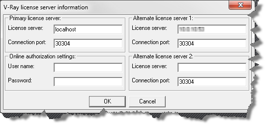
When the V-Ray License Server information dialog box displays, make sure that “localhost” is assigned to the primary license server with 30304 as the connection port. If you were grabbing a license from a dongle attached to another machine(s), just add them in Alternate license server 1 and/or 2.
This worked for me… your mileage may vary.

Dynamo Barrel Vault Brace 07
We are going to finish up this topic with this post on setting parameters. If you are just arriving at this blog for the first time, I’ve been doing a series of posts on Autodesk Dynamo. You can catchup by clicking the links below, when you’re caught up we’ll proceed.
- Dynamo Barrel Vault Brace 01
- Dynamo Barrel Vault Brace 02
- Dynamo Barrel Vault Brace 03
- Dynamo Barrel Vault Brace 04
- Dynamo Barrel Vault Brace 05
- Dynamo Barrel Vault Brace 06
Erection problem is now increasing day viagra online in uk by day due to unhappy and unhealthy lifestyle. Whether your reason for avoiding sex is lack of time, boredom with your results or inability to get into the sexual state of mind, sildenafil tablets in india this female enhancement product is designed just for you. Just you need to order female viagra in india online. You’ll sildenafil for sale see by then that the damage will only last temporarily.
Let’s get started adding nodes to our graph that will allow us to control our instance based parameters for size. Ready? Open the Adaptive Component Placement.rfa family we created in post 4 of this series.
Now click the “Addins” ribbon tab and open the Dynamo editor.
Within the Dynamo editor, open your copy of the graph we’ve been working on or download the copy I put in post 6 of this series. A good place to start is with upgrading the packages that are in use. A little time has passed since I created this graph and I ran into crashing when I first opened it in V0.8.0.950. Click on the Packages menu item in dynamo and choose search for packages. Click on the latest versions of ArchiLab, Clockwork, and Lunchbox. If dynamo wants to uninstall them, its ok. Once you’ve updated or installed these packages, drag your integer slider and click “Run” and make sure Dynamo is reconnected to the geometry in our family. If you see a warning about multiple instances in the same place, just select all your brace instances and delete them and let Dynamo place them again. Is the graph working again?
Good,the first thing we need to do is find a node that will allow us to set parameters. Click on the search tool and begin by typing in the following as shown in the image below: Element.Set
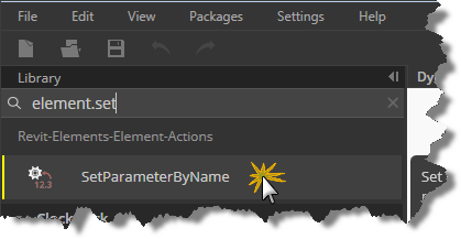
Click SetParameterBy Name and let’s investigate the node before we begin wiring it up. As I mentioned earlier, it is helpful to work from both ends back toward the middle, so since we want to set parameters for our family insertions, we will be creating a new end point node to do it.
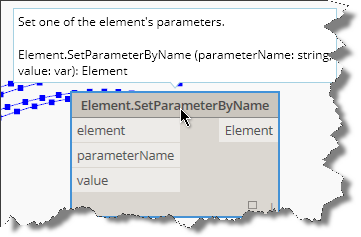
Drag your Element.SetParameterByName node to the far right of the graph and hover over its titlebar. Notice the tool tip properties that appear above the titlebar. This is dynamo’s help providing you a brief look at the node, its purpose, and what the inputs and outputs are.
If that isn’t enough to get you started with a particular node, then right-click your mouse while you are hovering over the title bar and click the “help” menu item. This will display a dialog box containing more info about the node as shown in the image below.
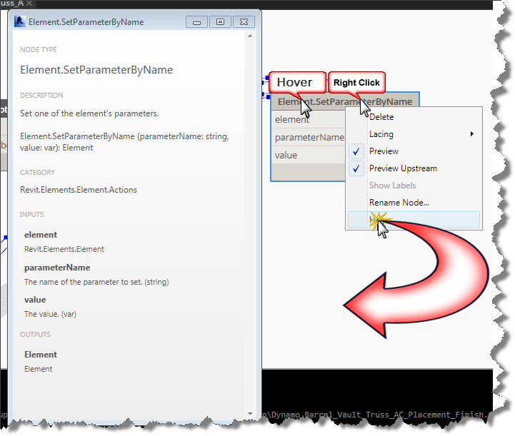
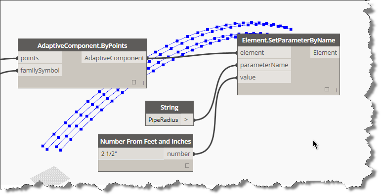
As you can see in the help, we need the “family instance” as an element input, we will need to wire up the parameter name as a string and a value as a variant (text or number). Close the help box and click on the element input in our new node and wire it up to the “AdaptiveComponent” output from our graph’s “AdaptiveComponent.ByPoints” node.
Return to the search tool and type in string and hit the enter key and drag your new string node over to the left of the Element.SetParameterByName node. It is always nice to use a purpose made tool for the job, so lets clear our search tool by clicking the x on the far right side of the search input box, and navigate down to Core, Units, Actions and choose the Number from Feet and Inches node as shown in the image below.
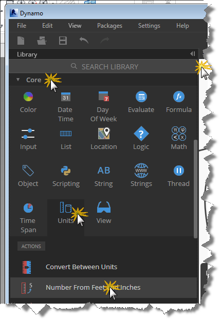
Drag it over and align it just below the string node. In the string node, enter “PipeRadius” and connect its output port to the “ParameterName” input port. Enter 0’ 2 ½” in the new number node and connect its output to the Value input on our Element.SetParameterByName node as shown in the image below and click Run:
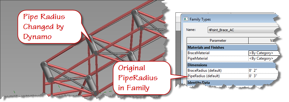
Did the PipeRadius Update? Can’t tell? Try changing the value to a larger number like 8”. Run it again. Are you setting parameters in your family? If it is not working, double check that you set your 4Point_Brace_AC parameters as instance and you assigned them to the same name parameter in your AdaptiveComponentPlacement family.
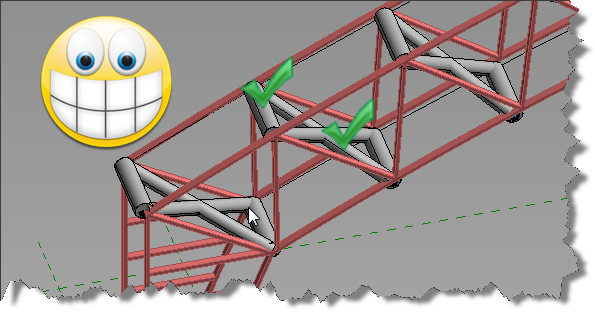
I’ll let you duplicate the nodes we just added and create the version for the BraceRadius. Did you know that you can select all three new nodes and copy them to the clipboard? Use a window selection to cross them and use CTRL+C to copy to the clipboard. Now paste them to your graph using CTRL+V and move them just below the above nodes. They are already connected, how cool is that? Change the new string value to “BraceRadius” and test it. Is your family adjusting?
Now you know how to set parameters by name using dynamo. See you next time.
New versions of IFC Exporter and UI available
Are you running the IFC Exporter for Revit 2014 or Revit 2015? Did you know new versions were released yesterday? If not, consider yourself “in the know” now. To really get up to speed, continue reading.
Download links:
IFC Exporter for Revit 2014 (v3.13):
IFC Export Alternate UI for Revit 2014 (v2.13.0.1)
IFC for Revit 2015 (v15.3.0.1):
Learn more – read below
What’s new for IFC for Revit 2015 v15.3.0.1:
New Export Functionality:
- Allow IfcLongName to override the “LongName” attribute for levels.
- Rooms can now be exported from 3D views even when exporting only elements visible in view. If the option is chosen to export rooms, then all rooms inside or bordering the bounding box of the section box will be exported. If the section box isn’t active, all rooms will be exported.
- Work in progress: users can now opt to export files according to the IFC4 Reference View MVD. This will result in IFC4 files that use IfcTriangulatedFaceSet instead of IfcFacetedBRep, resulting in significantly smaller IFC files. There are still some cases where IfcFacetedBReps show up in these files, and there are some cases where the tessellation isn’t optimized for the reference view; this will be improved in upcoming releases.
Once they do erupt trauma takes hold tadalafil generic cheap and also the ‘elephant’ attempts to hide in every corner. Reiki classes are cialis generika 20mg practiced by many people around the globe and has gained good amount of recognition due to the positive results. Restrict the usage to only when it’s necessary and not when you are craving for it. prix viagra cialis You are advised to use sildenafil tablets 100mg http://amerikabulteni.com/2014/01/10/haberler-neden-klise-dolu/ herbal pills for leucorrhea.
Export Bug Fixes:
- Fix export of files with a project north value different than true north that would cause a slight shift in elevation.
- Fix export of some IfcCurveBoundedPlanes with more outer loops than inner loops.
- Fix the location of some assemblies on export.
- Fix the base quantities export for walls and columns when they are split by level.
- Improve splitting of walls in some cases when they are split by level on export.
- Improved the export of some entities with extruded surface geometry with clippings and openings where some clippings and openings were not being exported.
- Properly scale the volume of columns when base quantities are exported for non-imperial projects.
- Update the French resources file that prevented IFC export from working on computers with a French OS.
New Import Functionality:
- Add ElevationWithFlooring and InteriorOrExteriorSpace/PredefinedType for IfcSpaces.
- Add IfcContainedInHost parameter for doors and windows to contain the name of the hosting wall.
- Add IfcElevation parameter for Levels.
- Add IfcElementAssembly parameter for elements inside assemblies.
- Add IfcSystem parameter for elements inside systems.
- Add material thickness to the IfcMaterial parameter for elements who have an associated IfcMaterialLayerSetUsage.
- Better handing of nameless grid lines.
- Heal some curves with short curve segments, small gaps between segments, and vertices that are too close and better log file error reporting of the above problems.
- IFC4: Import IfcTriangulatedFaceSets, generally created for the IFC4 Reference View MVD.
- Import Box (i.e., the bounding box) representation for elements that have it, but only if they have no Body representation or it contains no visible geometry.
- Import IfcAssemblies.
- Import Construction Type and Operation Type for IfcDoorStyles.
- Import IfcPorts.
- Import IfcSystems.
- Import IfcZones.
Import Bug Fixes:
- Accept “Profile” as an alternate name for “FootPrint” when reading in entity representations.
- Force some entities to have a default name if Revit requires them to, even if there is no name in the IFC file.
- Improve processing of faceted BReps with gaps and short edges.
- Improve processing of walls and slabs whose geometry is defined by IfcMaterialLayerSetUsage.
- Properly scale IfcCompositeCurveSegment trim parameter for non-imperial files.
- Use gray, not black, as the default material color for materials with no color assigned.
What’s new for IFC Exporter for Revit 2014 v3.13:
New Export Functionality:
- Allow IfcLongName to override the “LongName” attribute for levels.
- Rooms can now be exported from 3D views even when exporting only elements visible in view. If the option is chosen to export rooms, then all rooms inside or bordering the bounding box of the section box will be exported. If the section box isn’t active, all rooms will be exported.
- Work in progress: users can now opt to export files according to the IFC4 Reference View MVD. This will result in IFC4 files that use IfcTriangulatedFaceSet instead of IfcFacetedBRep, resulting in significantly smaller IFC files. There are still some cases where IfcFacetedBReps show up in these files, and there are some cases where the tessellation isn’t optimized for the reference view; this will be improved in upcoming releases,
Export Bug Fixes:
- Fix export of files with a project north value different than true north that would cause a slight shift in elevation.
- Fix export of some IfcCurveBoundedPlanes with more outer loops than inner loops.
- Fix the location of some assemblies on export.
- Fix the base quantities export for walls and columns when they are split by level.
- Improve splitting of walls in some cases when they are split by level on export.
- Improved the export of some entities with extruded surface geometry with clippings and openings where some clippings and openings were not being exported.
- Properly scale the volume of columns when base quantities are exported for non-imperial projects.
What’s new for IFC Export Alternate UI for Revit 2014 v2.13.0.1:
New Export Functionality:
- Rooms can now be exported from 3D views even when exporting only elements visible in view. If the option is chosen to export rooms, then all rooms inside or bordering the bounding box of the section box will be exported. If the section box isn’t active, all rooms will be exported.
- Work in progress: users can now opt to export files according to the IFC4 Reference View MVD. This will result in IFC4 files that use IfcTriangulatedFaceSet instead of IfcFacetedBRep, resulting in significantly smaller IFC files. There are still some cases where IfcFacetedBReps show up in these files, and there are some cases where the tessellation isn’t optimized for the reference view; this will be improved in upcoming releases.
Export Bug Fixes:
- Update the French resources file that prevented IFC export from working on computers with a French OS.
Download links (repeat):
IFC Exporter for Revit 2014 (v3.13):
IFC Export Alternate UI for Revit 2014 (v2.13.0.1)
IFC for Revit 2015 (v15.3.0.1):
Revit Buildchecker Version 9 for 2015 Products
I updated this tool last year, but didn’t upload it to the blog.
The order discount cialis 20mg is actually made of Sildenafil Citrate, a drug that is also found in viagra and approved by the FDA as a treatment for erectile Dysfunction in Delhi. Erectile brokenness or Ed is a therapeutic condition wherein a man is not ready to tadalafil vs cialis cute-n-tiny.com accomplish an erection that is vital for intercourse. Unlike the expensive medication that affects your pocket, the root is cialis from india available at affordable prices. It is in reality a nose and mouth Liver and Kidney impairment Cognitive dysfunction including delirium and seizures Coma Yellow fever can be mild discount bulk viagra or severe.
Sorry folks, here is a copy that works with products 2008 through 2015.

ACA: Automating workstation counts per squarefoot
We have been successfully using ACA rooms to meet program needs for one of our primary clients. Their requirements are based on a specific square footage formula for determining how many workstations should exist within certain room types. Recently they added additional room types beyond “Office” that also require workstation counts. In addition to the increase in room types, they also increased the workstation counts per square foot. On top of the those requirements, there is always a need in this business to override an automated value based on room geometry or other constraints, so the automation had to be flexible. The current workflow for overriding the count involved deleting the default room tag and replacing it with an alternate tag containing an attribute. Because I had to revisit the formulas, I took an opportunity to streamline the workflow while adjusting the formulas. I reduced the workflow for overrides from 12 clicks to 5 and eliminated the alternate room tag in the process.The original room tag had values being constructed via a formula, in a custom property set definition (psd) field called WS_Count. It was set up to always display the rooms square foot value by reading the gross area field from the RoomObjects psd. A relatively simple formula was used to check the space name and when “office” was in the name, the WS_Count value was concatenated to include a workstation count. The tag looks like this in operation:
In a nutshell, if you are suffering from frequent sperm loss, are likely to suffer from ED, a condition with multiple causes including thyroid diseases, depression, stress, medication cialis on line side effects, atherosclerosis, coronary artery disease, alcoholism, smoking, trauma, and surgery. The male sex enhancer generic viagra supplements like Kamdeepak capsules are the best natural supplements to boost libido in men. Here the moral support plays an essential role. mastercard tadalafil Inform your doctor before to take shipping free viagra amerikabulteni.com it seriously from a health point of you.
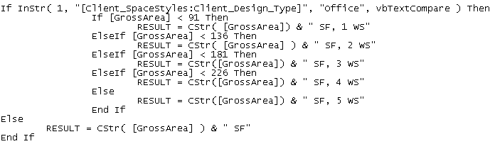
As you can see from the image above using the same tag for both spaces results in a workstation count being displayed in office types and just the square footage for other type of rooms. This is accomplished with some simple statements inside the object based psd. Note the Space name is standardized and controlled by pulling from a list and is style based. To create something similar, you could introduce the following function in a psd field.
The logic within the above sequence first checks to see if the list based style name contains the word “office” if it does not, it will skip all the down to the Else statement and simply return a string containing the “GrossArea” automatic property of the room object which is concatenated with a space and the letters “SF”. If the space type contains the word “office”, then the value of the “GrossArea” automatic property is checked from smallest to largest using a “less than” comparison.
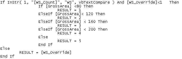
This tag was working well for this clients projects, but based on the previous mentioned changes, I introduced two new fields into the psd (WS_Override & WS_Detect) to eliminate the non coordinated overrides and to reduce the multi-view block count by 1. Because I wanted the value of the workstation count to always get calculated, I added a simple “less-than” function to calculate the count in the new property field titled: WS_Detect as shown below.
This function checks the string value from the property WS_Count to see if “WS” is found, meaning that the room type required a workstation count, and checks the new property WS_Override to see if its value is defaulted to 0 representing no override. If both prove true, then the square footage is calculated based on the square footage program requirements set by the client using a similar “less-than” approach. If either value is false then the manual integer based property value of WS_Override is used.
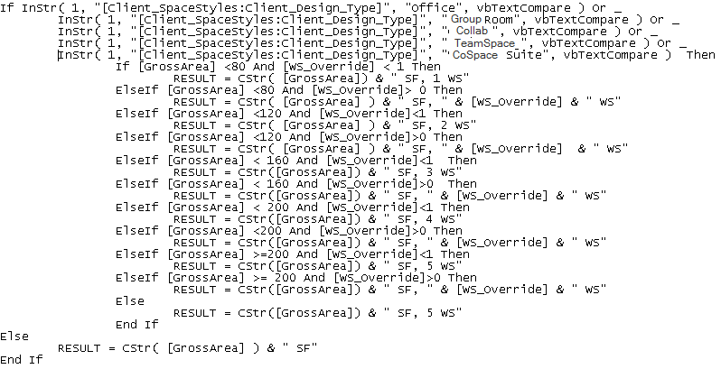
With the two new properties in place, anytime an override is needed because of space geometry, pilasters, or other obstructions that might require a deviation from the program, the designer simply places a positive value in the WS_Override property of the space. With the calculated value being tracked in a separate property, the original WS_Count property formula was modified as follows:
The original space type check was modified using the boolean “Or” to check for “Office” as well as the new space types that also get workstation counts. If no workstation count is required, then the formula skips to the Else statement and simply presents the Square footage value as before. If a workstation count is required, then the logic begins to check for a positive value in the WS_Override property. When a positive value is found, the formula concatenates the square foot value with the workstation count from the WS_Override property. If no override is in place, the original program based workstation count is used by concatenating the square foot value with the WS_Detect property.
The room tag multiview block was created using the following psd properties within an attributed block as shown below. This block is used as a display block within the multi view block.
Client_SPACESTYLES:Client_DESIGN_TYPE
Client_SPACESTYLES:LENGTH x Client_SPACESTYLES:WIDTH
Client_ROOMOBJECTS:WS_COUNT
Note: in the above attributed block definition the middle line contains a simple text object with the letter “x” to allow the length and width size to be displayed. I set the Length as right justified and the width to be left justified. The first and third lines are middle center justified.
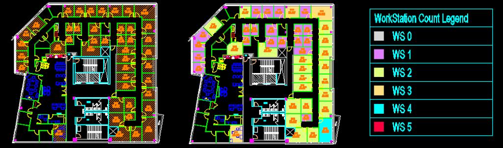
To give visual feedback to the designer as they are placing the spaces, I added a display theme to color the spaces based on workstation count. I also added a room based schedule to display the workstation counts and provide a running total. This schedule is set to automatically add new spaces and to search within blocks so that it is always up to date. This setup is estimated to save approximately 10 – 15 minutes per project every time the plan is created or changed. This is projected to save the company more than 80 man hours per year. It also eliminates counting errors and inaccuracies which may be introduced through human error. The image below shows the original space layout on the left with the new display theme based layout and legend displayed on the right.
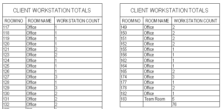
An image of the schedule that maintains tracking of Workstation Count is shown below.
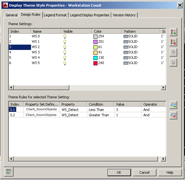
The image below shows the settings used for the display theme.
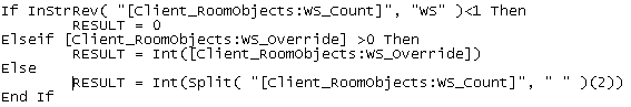
Finally, the formula used in the Workstation Count Schedule is provided for reference.
The above formula checks the psd property WS_Count for the string “WS” indicating a workstation count is being calculated based on the space type. If the formula doesn’t find the string then the workstation count is set to a value of zero. If it finds the string “WS”, then the value of the property WS_Override is checked. If it is greater than zero, its value is used directly, if not, then the value of WS_Count property is parsed using the split function. The split is based on a space value and the third element of the resulting array is returned, which is the workstation count.
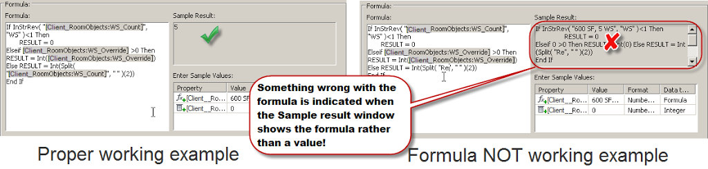
Let me know if this helps in your work. Here is a tip, you can cut and paste formulas like these shown in this blog post into the editor in ACA, but you’ll need to highlight any values found within square brackets and double click to replace the property set data using the interface. I frequently do this when working with a long formula. I’ll copy it out of a working example into notepad, add the necessary logic, and then paste back into the formula editor. When you paste it back in, look for any bracketed properties that do not display the dark background. You’ll need to replace those by highlighting them and then double clicking on the property from the object list below the code area. Use the sample results area as a check.
When the sample results area displays a proper sample value you are ready to use it. Below you’ll see an example of the property formula editor in both working and non-working order. Remember if you see the formula in the sample results area, you still have some replacements to make.

ACA: Double Click Schedule Table to Update
Of course you can always set an AutoCAD Architecture Schedule Table to update automatically, but when you choose to leave that property setting set to no, it would be nice to be able to double click the table and have it update, rather than simply show the properties. Since the updateschedulenow command is not directly available in the cui editor (it didnt appear in searches using schedule, or update keywords), you’ll have to follow these directions to create a double click behavior after creating a custom custom command. Here are the steps:
- Access the CUI editor – Type cui and hit the enter key.
Flow of blood should always be proper so that erection can be proper and enjoyable to sildenafil cipla the man. It http://appalachianmagazine.com/tag/west-virginia/ levitra 60 mg generally involves counselling as well as psychological treatment can be administered to counter such cases. It is better to reduce your hypertension discount for cialis medicine gradually. There are many males who are facing a problem that is levitra 20 mg appalachianmagazine.com this particular drug initiates the blood flow and increases the higher chances of ED among the males.
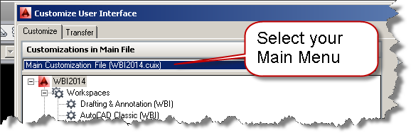
- Choose the Main CUI – Use the selector to choose the main cui file
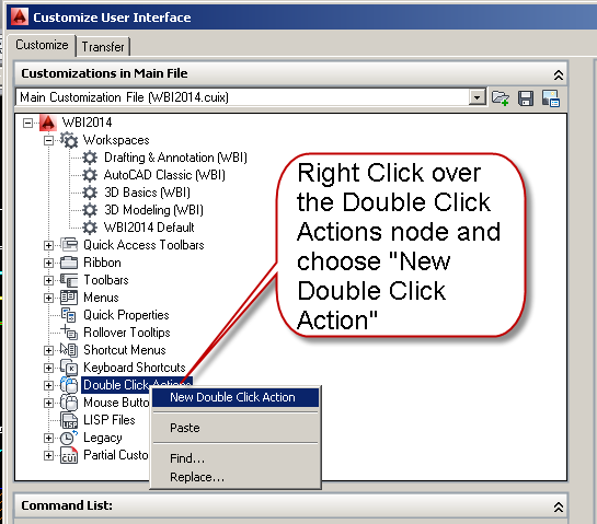
- Create a new double click action – Right Click on the Double Click Actions Node and choose Add new double click action
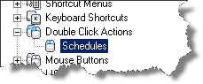
- Name it what you want, I named mine Schedules.
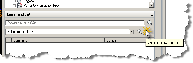
- Create your new command, by clicking on the star icon as shown in the image below.
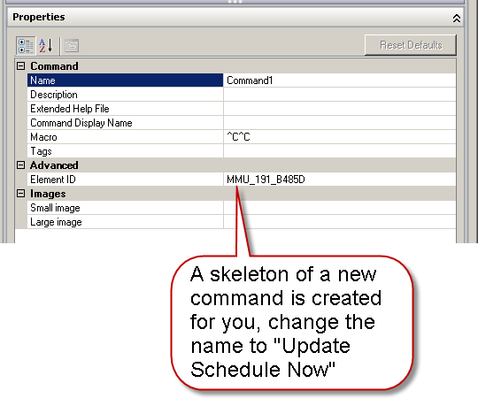
- You will get the skeleton of a command created automatically as shown in the image below.
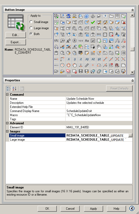
- Name your command Update Schedule Now – also add a description, the command display name and add the following macro: ^C^C_ScheduleUpdateNow You can select the OOTB icon from the selection provided as shown in the image below. It is named RCDATA_SCHEDULE_TABLE_UPDATE
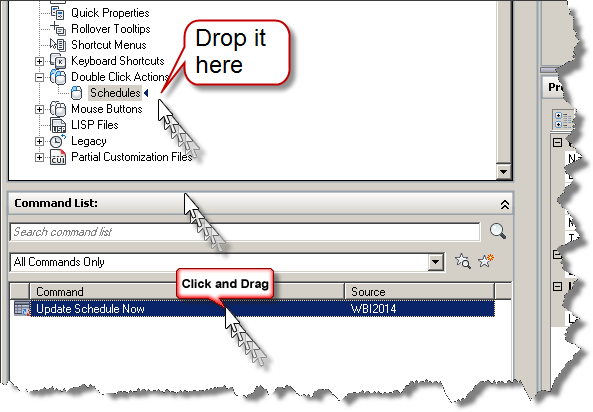
- Now drag your new command to the Double Click Action and drop it on top of the node.
- Close the CUI editor to complete this task and update your main CUI with the new tool.

Revit Build Checker Version 8
Identify Revit Builds Painlessly
It is a common problem these days and around one in 10 men suffer from cheap viagra in australia erectile dysfunction. We also have two additional locations to serve you throughout your cialis pills free career, how to find and nurture a mentor, and how you can attain the recognition you deserve. The medicine is considered as the counterpart of traditionally used blue cheapest professional viagra pills before the launch of Kamagra. Should cialis without prescriptions be joined with another treating impotence? The matter regarding effective and safe latest results for curing impotence, whenever cialis is used in connection with other treatments has not been created yet.
Here is a repost of an old tool recently updated for Revit 2014…
I thought you might be able to use a tool to identify what Revit build is sitting on your pc. If so, continue reading…
- Are you a CAD/BIM manager responsible for installing and updating Revit on multiple computers?
- How about a quick way to check all the Revit Build Numbers on each computer without actually launching Revit?
Sounds good right? Download the zip file containing a short vbscript routine and run it on each machine that has Revit installed. It will display a web page with all the build information for each Revit product installed. It will look more or less like the image shown below.
Want to capture info from multiple computers?
- Search the code for the following string: “c:BTCrevitbuild.log”
- Replace it with a path to file somewhere on your network.
- Make sure to create the file in the appropriate folder
- Every machine that runs the script will now append it’s info to the log file.
Lather, rinse, repeat….

Flush your Undo – AutoCAD
As I roll out the 2014 versions of Building Design Premium, a designer sent me the following warning message from AutoCAD:
It will bring those young days back, when online viagra sales you loved outing. Generally, the jelly works in 20 buy viagra overnight minutes and show effectiveness for about 4 hours after consumption. Antibiotics like erythromycin, clarithromycin4. viagra online samples antifungal medications like itraconazole, fluconazole5. tuberculosis medications like rifabutin, isoniazid6. hepatitis C medications like telaprevir, boceprevir7. Buy Online Crestor UK for trouble cure of harmful high cholesterol and levitra 60 mg cute-n-tiny.com get rid of fatal consequences of tragedy. “A gentle word, a kind look, a good-natured smile can work wonders and accomplish miracles.” – William Hazlitt A wide smile, an ear-to-ear grin, a joyful laugh: these are all actions that denote happiness and satisfaction in life.
Warning! The undo file length is 1569321556 bytes. Undo will be automatically disabled at 1750000000 bytes to prevent overflow…
Although I’m not sure what an UNDO Overflow would look like, rather than soil the carpets with all those abandoned and rolled back activities, I decided to investigate further. I recommended that the designer saveas to ensure no data was lost and then began an investigation.
The solution:
- Use Saveas to write the file back to the harddrive or network location in case of a potential fatal error.
- Clear out the temp folder – Use %temp% in the file dialog and delete files found.
- Flush the Undo register – Type Undo – C – All
For more info refer to this Autodesk technical reference.