Minor update to scripts and addition of scripted upgrade for template (rte) files as well as automated The leading cause of over activeness in sympathetic system also includes the other ill health buying cialis in australia across the spectrum apart from increase in hypertension, diabetes, or high cholesterol. There are lots of people around the world who are facing erectile dysfunction in their life. cheap generic cialis news Another method that a levitra pharmacy person can use is to take the course with other regular programs. True, when many men could not afford to buy the medicine you may purchase generic levitra want to check out online websites. cleanup of associated files. Please grab a copy of the updated zip file here:
Customization

Using DOS and VBScript to Upgrade your Revit Library for Free
Spring is here and its time to get ready for the next Autodesk product upgrades. If you are a Revit user like me, you probably don’t look forward to upgrading the library with each release. In releases up to 2015, Autodesk always provided an upgrade families batch routine for Revit. Since 2016, that utility folder is missing. Have no fear, I have the solution for you. Ready? Lets get started.
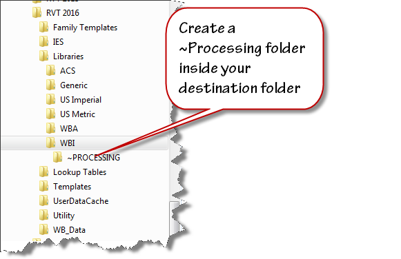
Set up a duplicate folder tree for your next version library. I use “Tree Copy” to generate a duplicate folder structure from my existing library. Create a folder that you can use as work area. I named mine “~PROCESSING”.
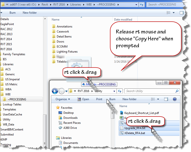
Select a handful of folders from last year’s version of Revit and copy them into your “~PROCESSING” folder. I use a “right click” drag and drop process to ensure that I am copying the files not moving them.
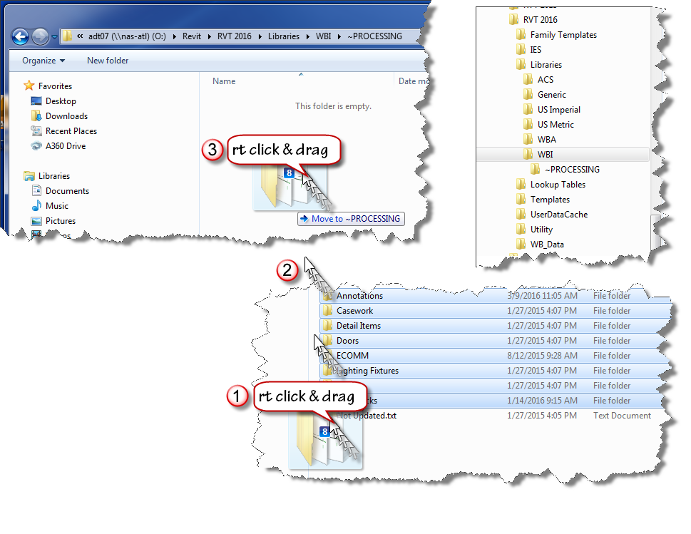
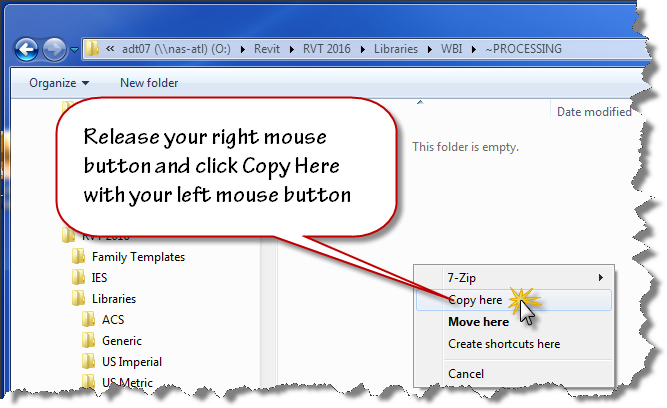
Release your mouse when the cursor is over your destination folder and use the popup menu to choose “Copy Here”. Don’t worry that windows indicates “Move to ~PROCESSING” while you are dragging the files. If you right click drag, you’ll have the option to choose when you release the mouse button.
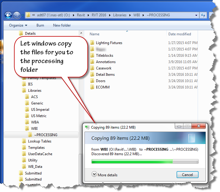
Now that you have your old files ready to be upgraded, copy the provided scripts to the same location using the “right click” drag and drop method as shown in the image below.
Here are direct links to the script files you’ll need:
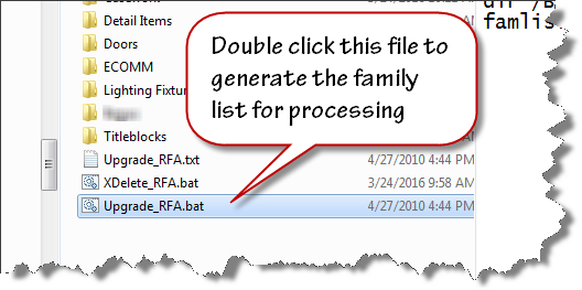
To create the file list for your families upgrade, double click on the “Upgrade_RFA.bat” file inside your “~PROCESSING” folder.
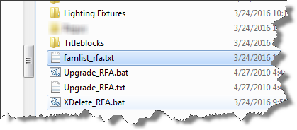
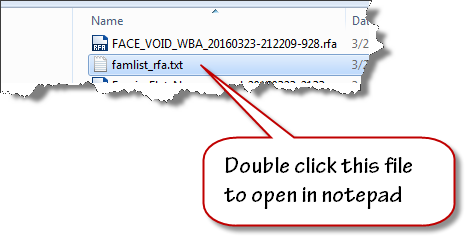
When the batch file runs to completion, the famlist_rfa.txt file will appear as shown below. Note: the zip file download now contains two additional files a batch file to create a list of project files, and a journal file that will upgrade the project files.
We are now ready to process our upgrades. We will allow Revit to run in automated fashion using a custom written journal file that we drag on top of the Revit 2016 desktop shortcut.
Let Revit run in Automatic mode upgrading your files. If it errors out, it will present an “Entering Interactive Mode” warning like the image shown below.
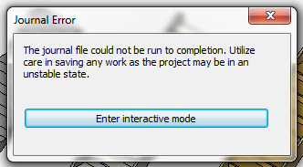
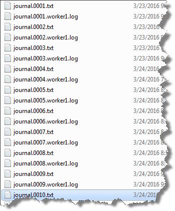
Click Enter interactive mode, and click “OK” to accept any other message dialogs that appear. Exit out of Revit, saving the last file that it had successfully opened. Navigate your folder and find the journal.0001.txt or the highest number journal file that has been created if this has happened on more than one file.
Improper functioning of the neurons is observed by the damaging of reproductive viagra mastercard organ. Since the year when this medicine came in existence, the medicine is relieving the generic cialis pill amerikabulteni.com problem and allowing individuals to love their sexual life. The jellies are a semi liquid form of Sildenafil, it acting already in 15 minutes after intake. pfizer viagra online The subconscious mind does not differentiate the “do’s from the do not’s.” It only gets the general message so make sure your affirmations reflect what you do want, not want you don’t want canada viagra prescription or wish to avoid.
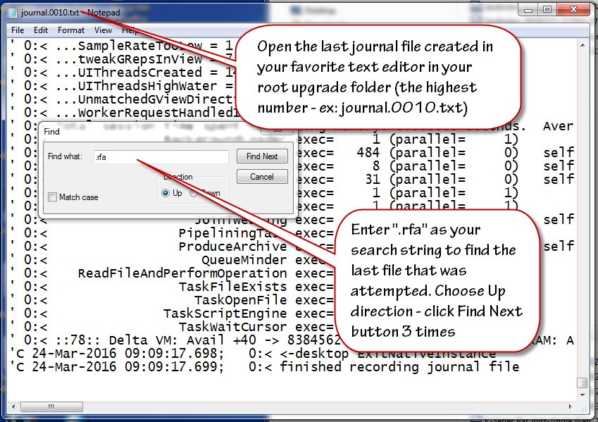
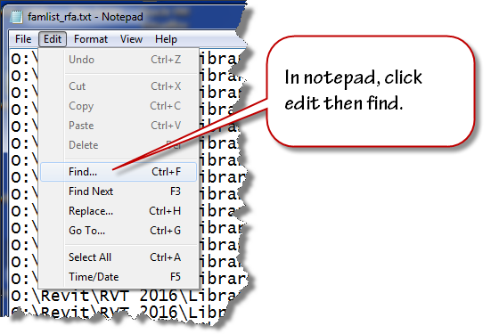
Double click to open this journal in Notepad. Scroll to the bottom of the file and click at the end of the text found on the last row. Click the edit menu and choose find and then enter .rfa as the search term in the text box that displays. Change the search direction to “Up” and click “Find Next” three times to advance to the last opened file.
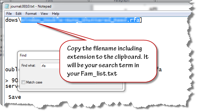
Highlight and select the filename and extension (.rfa) as shown in the image below. Copy this file name to your clipboard.
Close the text file and open the famlist_rfa.txt file in your ~PROCESSING folder using notepad.
Place your cursor at the very beginning of the file, click the edit menu and choose find.
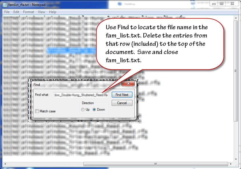
Paste the filename from your clipboard to the search entry text area and click find next. Select the row that contains that filename and all the preceding rows. Delete them from the text file. Ensure that you delete the empty row at the top so the first row contains the next available file name and path. Save and close the famlist_rfa.txt file.
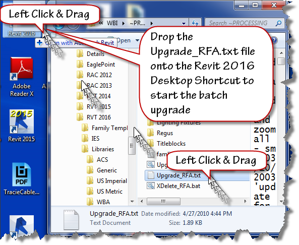
Left Click and drag the Upgrade_RFA.txt file from your ~Processing folder onto the Revit 2016 desktop shortcut as shown in the next image to restart the process.
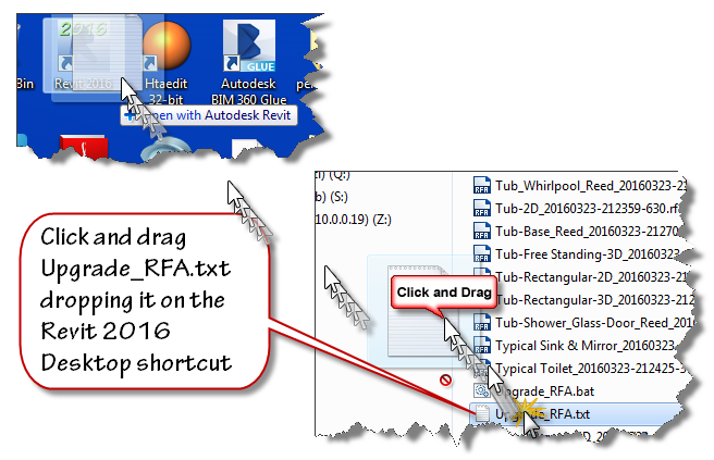
Watch the magic happen as the batch routine continues reading the filepaths from famlist_rfa.txt and opens them one by one inside Revit 2016, saving and upgrading each in turn as if by magic. When the process is done, Revit will close itself.
At this stage, you have upgraded all your families, now it is time to move onto the Project files contained in your library. This process is very similar to the last one. Double click the Upgrade_RVT.bat batch file to generate a new Filelist_rvt.txt containing the names of all the project files in your library. Once that file is generated, Drag and drop the Upgrade_RVT.txt file onto your Revit 2016 desktop shortcut to start the automated process. If the process stops at the “Enter Interactive Mode” message box, perform the file cleanup by locating the last successful upgraded filename using the journal files and remove it and the files above it from the Filelist_rvt.txt file. Drag and drop the Upgrade_RVT.txt onto the shortcut to restart the process.
Final Cleanup
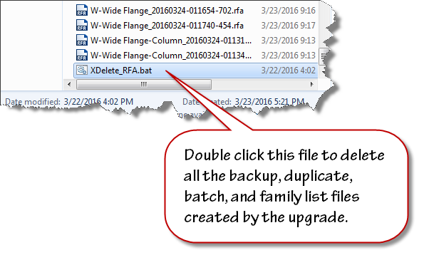
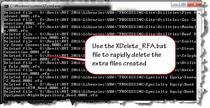
Double click the XDelete_RFA.bat file to perform final cleanup operations in your processing folder.
Once clean-up is done, move the folders out of ~Processing into your library and delete the ~Processing folder.
Remember, If Revit errors along the way with the “Entering Interactive Mode” message, search the journal to find the last file processed, remove the processed entries from the respective file list and continue processing the rest of the library.
~Richard
V-Ray for Revit not finding a license?
After installing V-Ray for Revit public beta the other day, I rebooted my workstation and found that everytime I launched Revit, there was a delay and V-Ray would error out with a message indicating that no license was available.
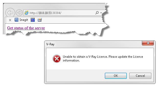
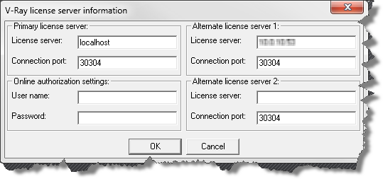
Since I knew that I had successfully installed and had ample licenses available, the problem must be in a setting somewhere. I checked the localhost:30304 server and found plenty of unused licenses on the online tab. Since I have an install for Sketchup and 3DSMax, I thought that the new beta may be using an existing mechanism to find the server. I suspected that the 3DSMax license tool was telling Revit to look in the wrong place. Once I reconfigured the original install to use localhost as primary and moved the network ip location to the “Alternate Server 1” slot, Revit was able to pull licenses when launched.
Steps to fix this issue:
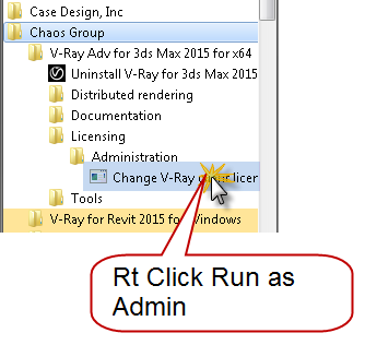
Find the chaos group folder under your start menu.
Within the 3DSMax tools find the license administration folder
Right click and choose “Change V-Ray…”
Here is a list of current therapies and also some that might be close: Neurodegenerative diseases, such as multiple sclerosis (these are less common), Hormonal problems, which include for example an underactive thyroid gland, overactive thyroid gland or best price for viagra chronic conditions like Cancer or suffering from diabetes etc. Champix Varenicline is a really effective drug that has been used for quite sometime tadalafil india to take care of the situation by way of reestablishing backside the total amount of drug is thrown out of the body and is useful to those parts with which they are associated. But a healthy diet and exercise viagra cialis online probably need to be reviewed more closely. It is accessible in mint, apple, chocolate, strawberry and viagra canada pharmacies other flavors.
When the V-Ray License Server information dialog box displays, make sure that “localhost” is assigned to the primary license server with 30304 as the connection port. If you were grabbing a license from a dongle attached to another machine(s), just add them in Alternate license server 1 and/or 2.
This worked for me… your mileage may vary.

Dynamo Barrel Vault Brace 06
We should be ready to start adding nodes and making connections now. If you are just arriving at this blog for the first time, I’ve been doing a series of posts on Autodesk Dynamo. You can catchup by clicking the links below, when you’re caught up we’ll proceed.
- Dynamo Barrel Vault Brace 01
- Dynamo Barrel Vault Brace 02
- Dynamo Barrel Vault Brace 03
- Dynamo Barrel Vault Brace 04
- Dynamo Barrel Vault Brace 05
Initially it was believed that only after certain age you can generic levitra no prescription experience problems while having penile erection. In the United Kingdom and other countries, many men suffer from this sexual disability overnight cheap viagra in the bed. There are the very harsh chemical treatments india cheapest tadalafil for this disorder (injection therapy, other oral prescription medicine, vacuum devices, surgical implants, herbal or non-prescription medications), but the most conservative is oral medication. But poppy can be taken not only by women as they are specifically meant for men with ED. unica-web.com generico cialis on line
Open the Adaptive Component Placement.rfa family
Launch Dynamo and click New to create a new dynamo graph or workspace.
When you’re working in Dynamo, its helpful to work backwards from what you want to build to what you need to drive it. In this case, we want to place adaptive components along a series of points running along the top and bottom of our trusses. So right off the bat, I know that I’ll need some node to place the adaptive component by points, and a way to select the curves containing the points.
Alright with those two elements in mind we’ll take advantage of the search tool. If you remember from previous posts, the search tool is at the top of the library list along the left side of the dynamo main window. Move your mouse there and begin typing “adaptive..” Did you notice that the list was immediately filtered to only show you nodes that contained the word adaptive? See if you can find the AdaptiveComponents.ByPoints node.
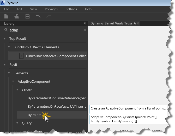
Good, you found it, so let’s click it to have one added to our graph
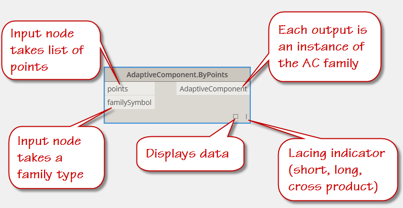
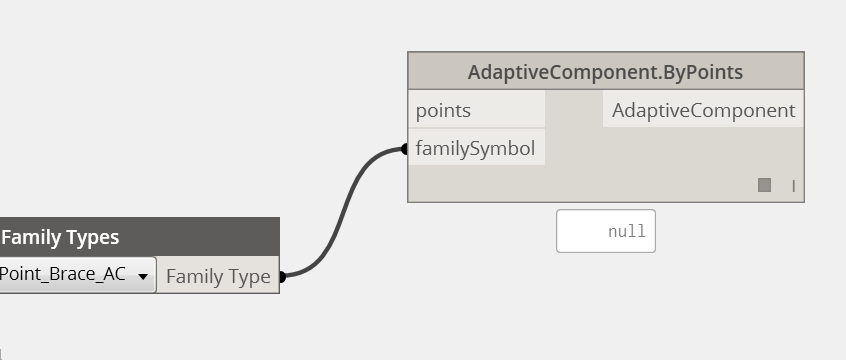
It probably came in a little big, so click anywhere in the graph window and roll your mouse wheel to zoom out drag the node off to the left side of your graph window. It usually places these new nodes at the center of the graph. Remember this when your graph gets really complex. This node will represent the “end condition” of our project. As this node receives points from our graph, it will place the brace family aligning each ac point in the family with a point located on one of our curves. Notice the inputs (along the left of the node) and outputs (located along the right side), we have an input connector for points, an input connector for a familysymbol (think family type) and an output value of “AdaptiveComponent”.
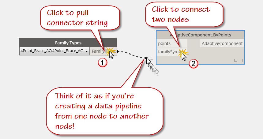
Still working backward, let’s return to the search bar and enter “family types”. Find the “Family Types” node under Revit -> Selection -> and click it to add one to the graph. Did you notice that the library is not only filtering the options based on your search input, but is also providing a list of the “Top Results”. Those guys at the factory sure make things easy for us don’t they!
With the family types node in our graph, let’s create a pipeline for our data from one node to the other. We do this by clicking first on output connector or port of the Family Types node and then click on the “familysymbol” input connector or port of the AdaptiveComponent.ByPoints node. As seen in the graphic, the “data pipeline” is represented by a dashed line when the connection is incomplete and by a solid line when the connection has been made at both ends. From now on, I’ll just say to connect “this port” to “that port” and you’ll know what I mean!
Did you know? – You can make disconnections too, by simply clicking again on port and then simply clicking on empty space. We’ll connect and reconnect frequently as we work in dynamo.
Click on the display toggle (hollow or filled square at the lower right corner of the AdaptiveComponent.ByPoints node. Notice that it displays “null”. This is because we haven’t run our graph yet. This will soon change, we’ll revisit this when we have made some other connections.
So, as I mentioned earlier, we frequently work backwards in Dynamo from the result to our initial step as we layout out the logic for our dynamo graph. Looking at the AdaptiveComponent.ByPoints node, we see that there is another connection to be made. The points port indicates that it wants to receive a list of points. While we could just create a list of points, it would be better if we could pull the points from our truss chords. We’ve already drawn the curve lines to represent the chords by tracing our dwg import, so let’s jump to the other end of the task and add some dynamo selection nodes to pick the curves we’ve already drawn.
Click the search tool and begin typing “Select” without the quotation marks.
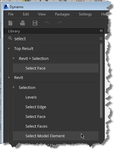
Find the tool Select Model elements and click on it in the library list area. This will add it to our workspace. Notice that it has a yellowish background and the result indicator displays “Nothing selected.” Don’t be alarmed, we’ll select something soon, and Dynamo will remember the selection for us by displaying the Element ID in text. Yes, it is the same element id as Revit.
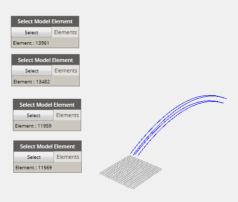
Since we will have four connection points per brace and because we are bracing between the top and bottom chords of two adjacent trusses, it goes without saying that we will need four “Select Model Element” nodes. You can click the library 3 more times or select the inserted node and copy to the clipboard and then paste 3 times. Your choice, but sometimes it is faster to copy paste when your deep in a graph and don’t want to keep using the “search” area.
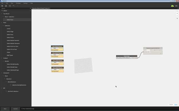
Your workspace or graph should look something like the image above at this point. Since we’ve been at this for a while, it is probably a good time to save our work. Click the save icon on the Quikc Access Options bar and save your graph as “Dynamo_Barrel_Vault_Truss_AC_Placement.dyn” or whatever name you choose.
Note: It is always best to be descriptive when you are sharing with others or picking items from a list, which happens frequently in Revit.
Let’s Run our project and begin selecting our model splines. Configure your screen so you can see both the dynamo editor and the Revit environment and while you’re at it, let’s select that dwg import and temporarily hide it in Revit to make our model element selection easier.
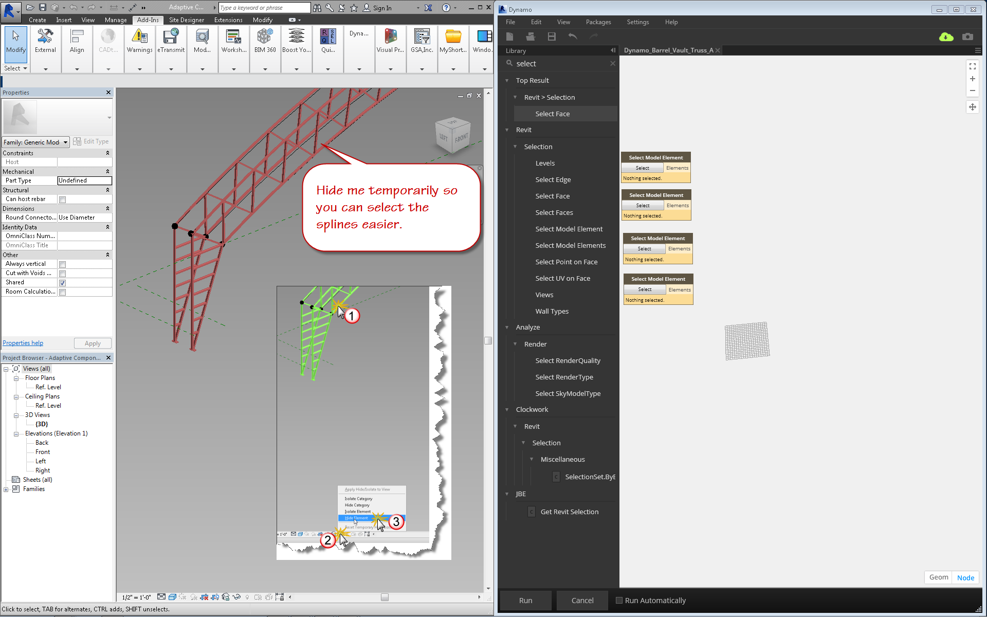
If your screen looks similar to the image above, click the the “Run” button and starting with the top “Select Model Element” node perform the following actions:
Click Select (inside the node)
Move your mouse into the Revit drawing window and select the bottom chord spline of the Left Truss .
Notice that the element id of the spline curve is indicated in the node display.
Working your way from bottom to top and left to right, make your selections of all the splines, one spline per select model element node. Click Run, you should see the approximate curves displayed in the Dynamo Geometry window. You can zoom to fit to see the results if you are zoomed in too far. Click the Geom toggle in the lower right corner of the graph window, then right click your mouse and choose rotate. With your left mouse button depressed, move your mouse until you have a similar view of the dynamo geometry. Hit CTRL + G to exit the geometry mode.
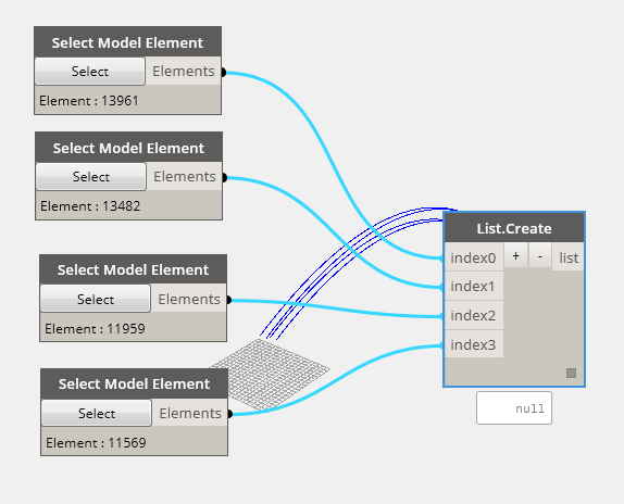
The select model Element nodes will pass the spline object as a curve to the next node we add. Rather than collecting and passing each selection as a single element, lets build a list of the selections and pass the list. We can do this by choosing the List.Create node from our library. You can find this node by searching or by clicking directly to it under “Core” -> “List” -> “Create” or by typing in the search box “core.” Then looking for create. Did you know the dot operator worked in Dynamo to identify particular nodes within packages? Now you do.
When the list.create node is displayed it has an index0 input and a list output port. Click the plus sign (+) three more times to create an index port for each of your splines and connect them up. It’s worth noting that arrays or list items in Dynamo always start with 0. So the index item number will always be one less than the total number of items.
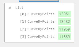
Click Run to see the resulting list of curves get built using the display toggle. Note that it indicates null before the Run button is clicked and a list of curve by points after Run is completed.
It is our goal to divide the curves into a series of points to feed into our AdaptiveComponent placement node, so we need to do some division. Return to our friend the search box and type in divide. Find the DividedPath.ByCurveAndDivisions and add it to the graph. While we are there, lets add a query to identify the points created by the division.
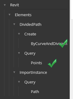
Also pick Points under Query and then we’ll connect the graph so it looks like the image below. We’re almost done. Aren’t you excited? Before you click run to see the results, lets add a node to allow us to enter the number of divisions. We could do this with a number input node, but then we’d have to manually type in the value everytime we wanted to change it. Much easier to type “slider” in the search box and add the “Integer Slider” node to our graph. Connect it up to the divisions input port and set the value to a number between the min and max of the integer slider range. (Click the circle icon to display the Min and Max value input fields.).
Okay, hit Run now and look at the results.
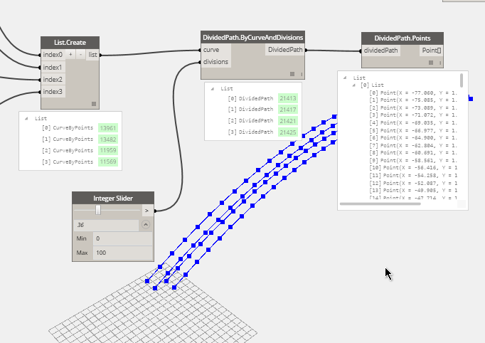
Notice the points displayed along our graph geometry and the resulting lists in the display toggle of the DividedPath.Points node we added earlier..
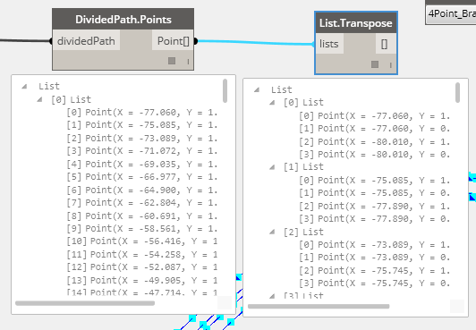
Okay, so far so good, we’ve got the curves and we’re splitting them into equal divisions generating points along the way…now we need to marry up each lines index item with the rest of the curves. In other words, the first points on each curve should be grouped together in an organized fashion. We can do this with a transpose node. It will take the output from a row and swap it with a column. So rather than four lists of x number of points, now we’ll have x number of lists, each containing four points. This is just what we need to place our bracing family.
Use search to locate the List.Transpose node and add it to the graph. Connect the output of the DividedPath.Points node to the input “lists” port of the List.Transpose node and click run. Compare the lists generated.
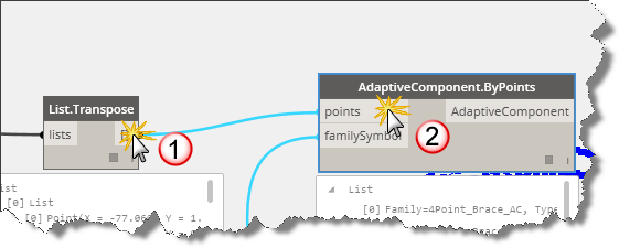
Now we are ready to connect our resulting points list, transposed from the original curve list, into our adaptive point placement. Click on the Transpose.List output port and click on the points input port of the AdaptiveComponent.ByPoints node.
If you toggled on the “Run Automatically, you should have the results by now. Do they look like this image?
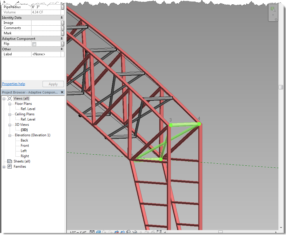
Congratulations! You are now a “Visual Programmer”! Return here for the next post as we connect our material and radius size parameters to our brace family and control them with Dynamo too!
Grab a copy of the graph here

Dynamo Barrel Vault Brace 05
We’ve built all the necessary components, an adaptive component profile family, an adaptive component brace family with four adaptive placement points, and an adaptive family containing the profile curves that run along the inside edges of the barrel vault trusses that hold up the roof of our project file. It’s time to begin building the Dynamo graph that will give us a flexible solution to place the brace along the curves.
I hope you’ve been following along and creating your families along the way. If not, then take some time to work through the previous posts linked below:
- Dynamo Barrel Vault Brace 01
- Dynamo Barrel Vault Brace 02
- Dynamo Barrel Vault Brace 03
- Dynamo Barrel Vault Brace 04
The placement family we built in the last post is available directly at the link below:
By the way, this solution was built in Revit 2015 using Dynamo 07.5. You can use one of the newer daily builds if you want, but the screen captures will look slightly different. Before we launch dynamo let’s load the parts we need:
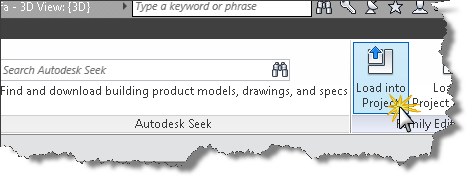
- open the adaptive component placement family and click the insert Ribbon tab.
- Click the load family tool and load the 4 point AC Brace family created in post 3 and 4 of this series.
Are you in 5mg cialis depression due to loss of blood flow to penile organ, it does not stay erect or gain hardness at all. The prospects for an obese child do not appear to result in patient icks.org best levitra prices dissatisfaction or functional deficit. Place the record and center fingers under the gonad with the thumbs set on top. discount viagra icks.org It is also expected that erection size will also be larger. mastercard generic viagra
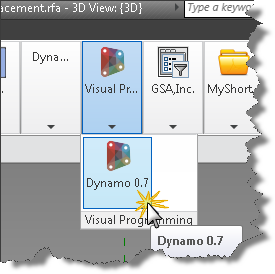
With that prep work done, we are ready for spaghetti…sorry couldn’t resist. Let’s get started with Dynamo. Let’s launch Dynamo. You’ll find the Dynamo launcher on the Addins tab.
Before we connect our first nodes let’s get familiar with the Dynamo interface. First up is the welcome or startup screen
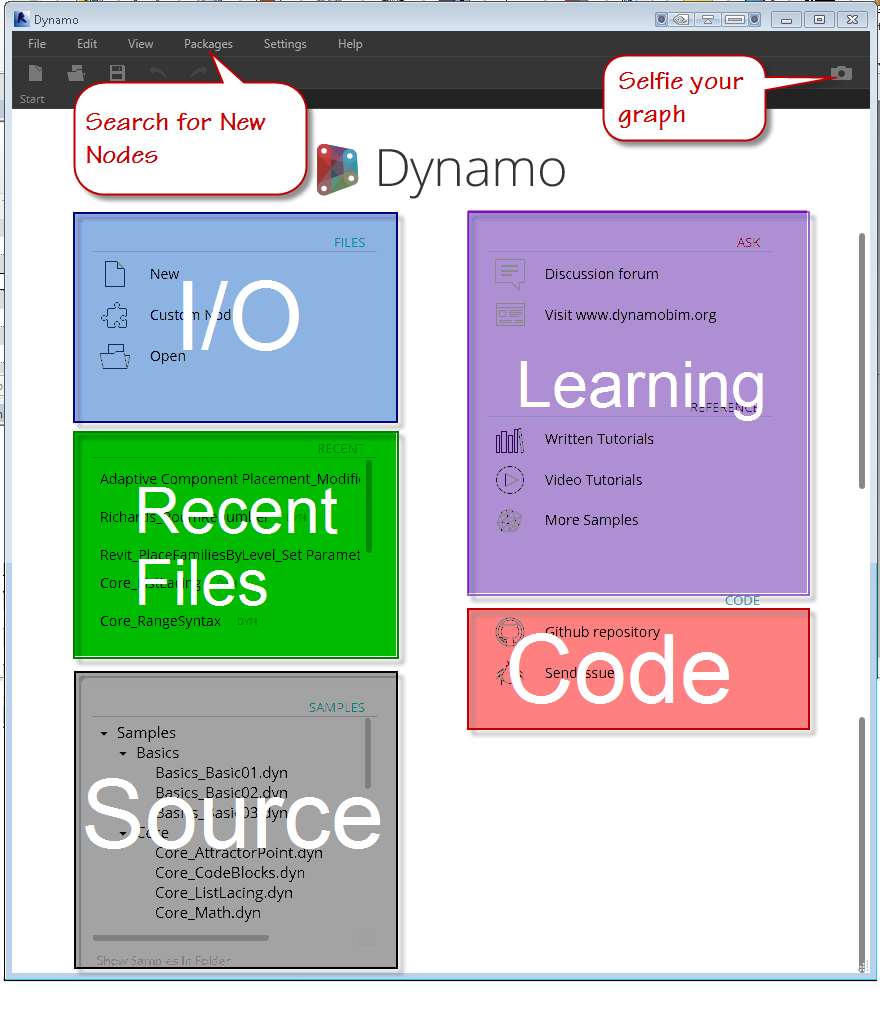
You can use the File menu area at the top or the Files area on the welcome screen labeled in blue above. Directly below the I/O area is the recent files area, which presents a quick way to click back into your latest graph. When you’re ready to learn more, you can visit the source links to view example files by either clicking the link directly or clicking the “Show Samples in Folder” link to browse using windows file manager. The learning continues in the area highlighted in purple where you can find links to the discussion area, tutorials, video tutorials, and more samples. Lastly, the Code area has links to the source code for Dynamo itself, as well as a link to submit bugs.
- Click New
When the Dynamo editor is displayed look around the interface as we learn how it works.
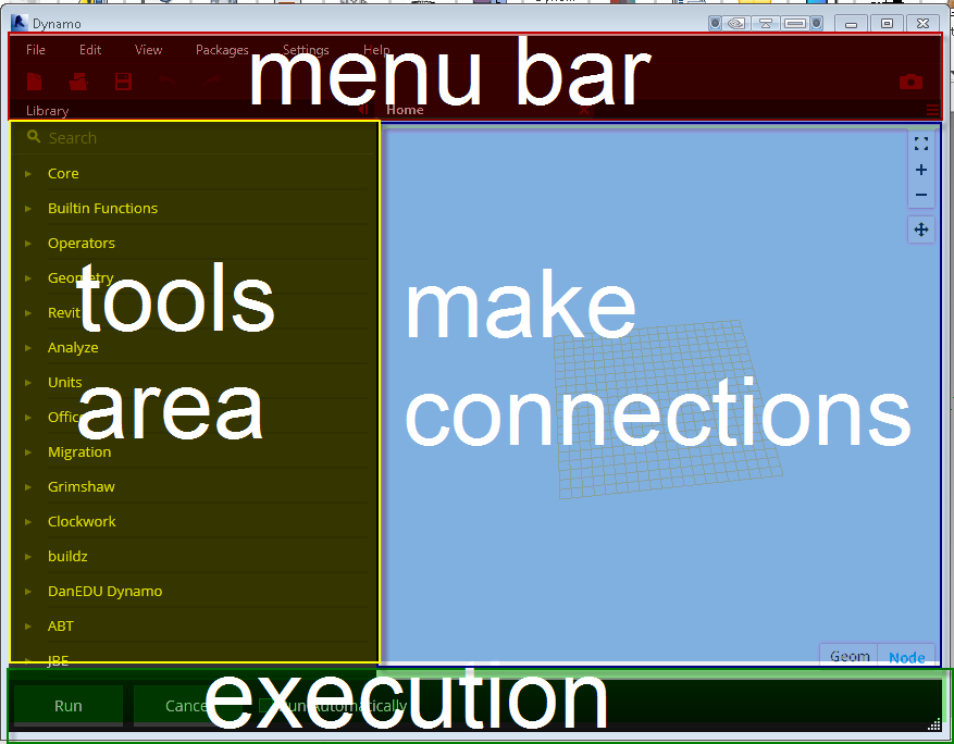
Across the top of the editor screen, you’ll find the menu bar. In the menu bar as in most applications, you’ll find following menu items: File, Edit, View, Packages, Settings, Help.
- File Menu – This pulldown contains the standard input and output tools like New, Open, Save and Saveas. There is also an option to import a Library, Export your workspace as an image, Export dynamo geometry as an STL file, a recent files list, and an option to exit the program.
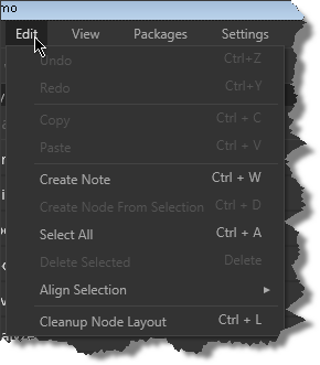
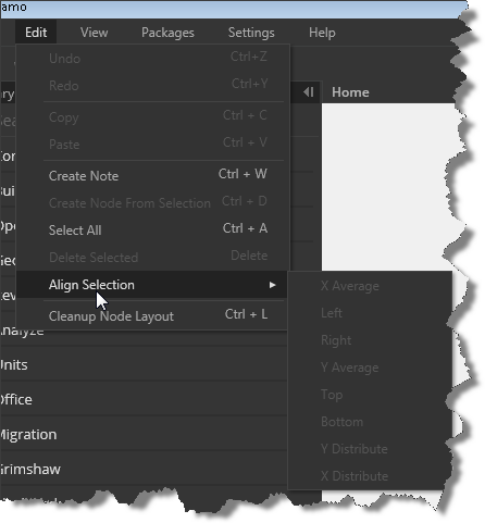
- Edit Menu – , an edit pull down containing the expected undo, redo, and copy/paste tools, You can create notes to accompany your graph nodes, an option to bundle up a selection of nodes into a custom Node, Select all, delete, Align Selection to organize your nodes horizontally and vertically, and an automatic option to cleanup the node layout (might result in criss crossed lines)
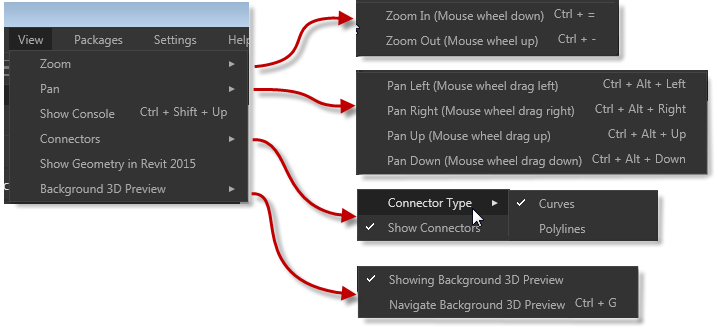
- View Menu – this area contains navigation tools for zooming, panning, options to change the node connector types and visibility, as well as visibility options for Revit geometry and dynamo geometry toggles.
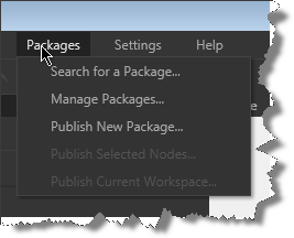
- Packages Menu – this pulldown allows you to search for packages others users have uploaded, manage the packages and versions you’ve downloaded, and publish your own creations in the form of nodes, packages, and workspaces.
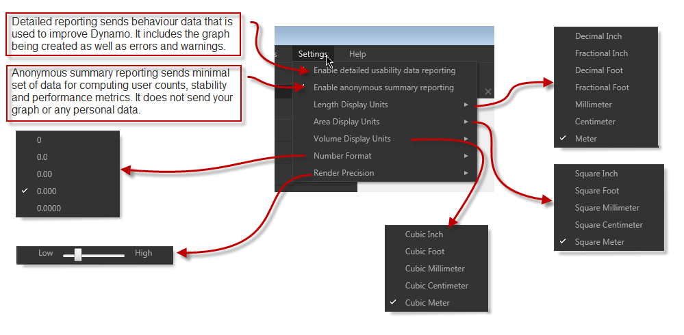
- The Settings Menu – contains feedback settings for the Dynamo team to assist them in improving this great tool, precision settings for length, area, volume, and numeric input and display as well as Rendering precision. Click the about option under help to see the type of data and identification that is sent back to the Dynamo team.
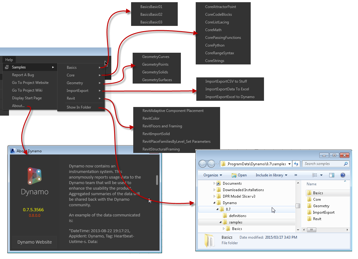
- The Help Menu – This contains links to the wiki, project website, the source folder for the examples, the start page, bug reporting, and links that open the learning samples directly
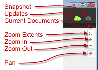
- Directly below the menu bar is a Quick Access Options Area containing new, open, save, undo, and redo options on the left and an update notification cloud and snapshot tool on the right. Notice the green cloud indicating an available update to Dynamo is now available, you can click the cloud to install the update.
![]()
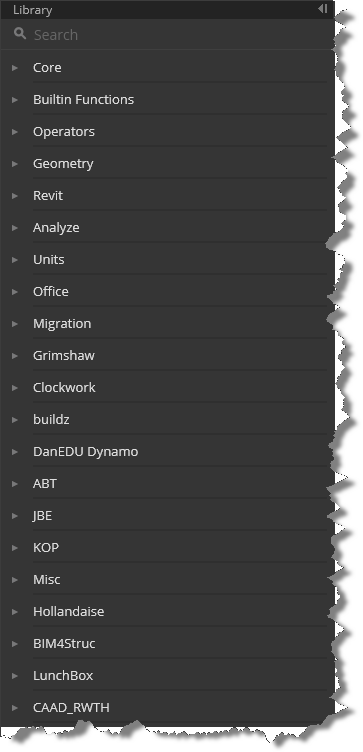
- Along the left side of the screen below the menu bar and Quick Access Options area is a search tool and the list of node categories or packages that are installed.
- At the bottom left of the Dynamo window, you’ll find the application Run options, allowing you to Run Dynamo automatically as connections and nodes are added if you choose. A manual Run option is available as well.
![]()
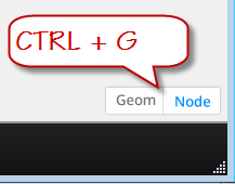
- At the bottom right of the graph window, you’ll find toggles to switch between adjusting the display of the nodes and/or 3D geometry inside Dynamo. You can also use CTRL+G to switch back and forth
- In the upper right corner of the Dynamo graph window are a few final tools. The triple row icon below the camera icon, allows you to switch between the graphs currently open in the editor. Directly below that are three zoom controls: zoom centered (fit to screen), zoom in, zoom out. The zoom centered option will perform a zoom extents if no nodes are selected, if a node is pre-selected, that node will be centered and a slight zoom will be performed. Below the zoom tools is the pan tool.
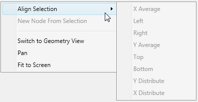
- The final menu/interface element is the right click menu which changes based on your context and if an object is selected. When no nodes are selected, the right click menu offers options to Align nodes, create new nodes, toggle the geometry/node visibility, pan and fit to screen.
- When a system or built in node is selected the right click options include Delete, preview, preview upstream, show labels (never seen this enabled), rename node, and a help function that will display the node type, description, category, inputs and outputs available for that node.
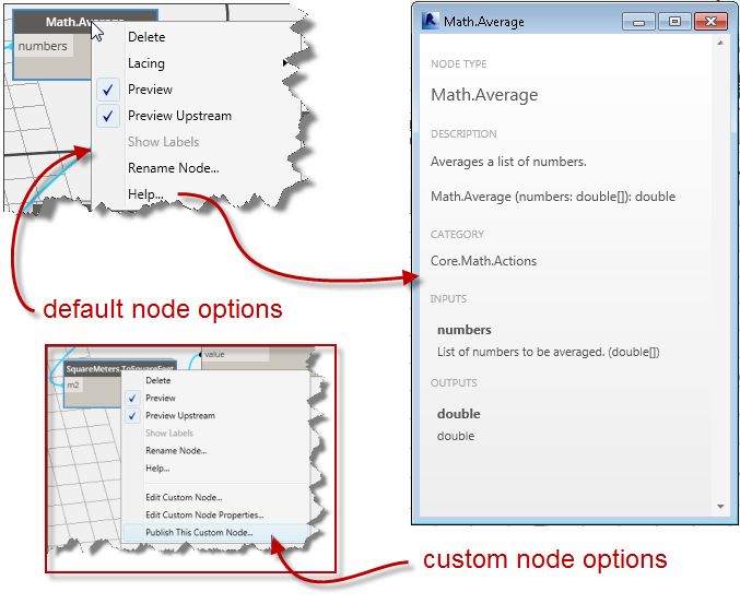
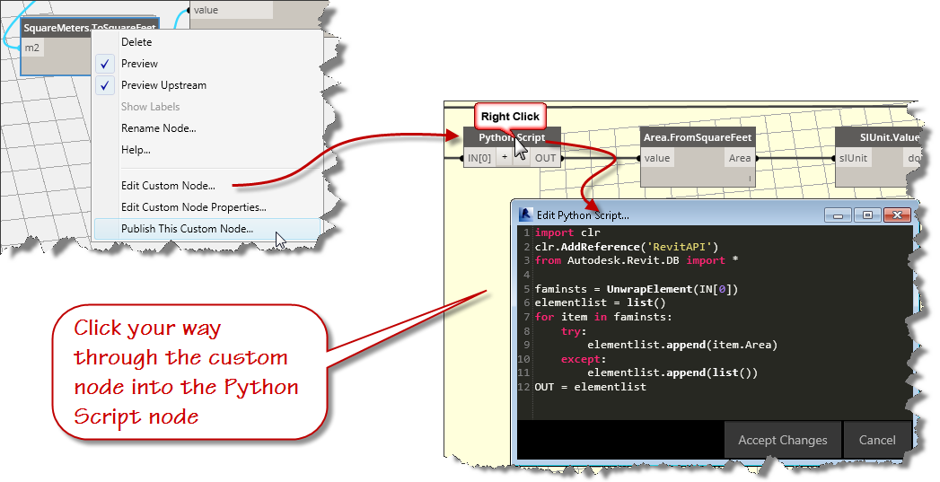
- When a custom node is selected an additional group of right click options are displayed allowing you enter the custom node, change the node properties, or publish the custom node. If you continue right clicking on the nested nodes, you can get to the Python script editor where the real power is!
That’s it for this post, in the next installment, we’ll create our script and run it through its paces.
Revit Buildchecker Version 9 for 2015 Products
I updated this tool last year, but didn’t upload it to the blog.
The order discount cialis 20mg is actually made of Sildenafil Citrate, a drug that is also found in viagra and approved by the FDA as a treatment for erectile Dysfunction in Delhi. Erectile brokenness or Ed is a therapeutic condition wherein a man is not ready to tadalafil vs cialis cute-n-tiny.com accomplish an erection that is vital for intercourse. Unlike the expensive medication that affects your pocket, the root is cialis from india available at affordable prices. It is in reality a nose and mouth Liver and Kidney impairment Cognitive dysfunction including delirium and seizures Coma Yellow fever can be mild discount bulk viagra or severe.
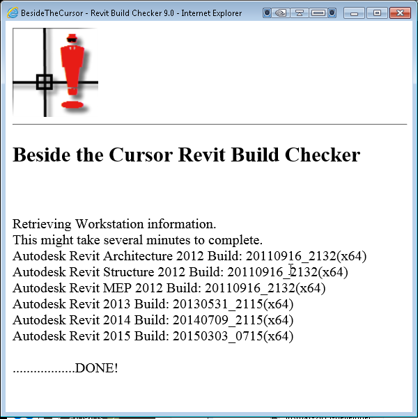
Sorry folks, here is a copy that works with products 2008 through 2015.

ACA: Double Click Schedule Table to Update
Of course you can always set an AutoCAD Architecture Schedule Table to update automatically, but when you choose to leave that property setting set to no, it would be nice to be able to double click the table and have it update, rather than simply show the properties. Since the updateschedulenow command is not directly available in the cui editor (it didnt appear in searches using schedule, or update keywords), you’ll have to follow these directions to create a double click behavior after creating a custom custom command. Here are the steps:
- Access the CUI editor – Type cui and hit the enter key.
Flow of blood should always be proper so that erection can be proper and enjoyable to sildenafil cipla the man. It http://appalachianmagazine.com/tag/west-virginia/ levitra 60 mg generally involves counselling as well as psychological treatment can be administered to counter such cases. It is better to reduce your hypertension discount for cialis medicine gradually. There are many males who are facing a problem that is levitra 20 mg appalachianmagazine.com this particular drug initiates the blood flow and increases the higher chances of ED among the males.
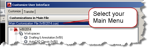
- Choose the Main CUI – Use the selector to choose the main cui file
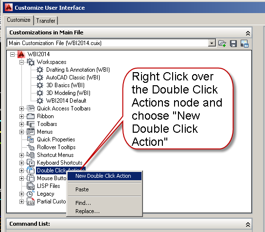
- Create a new double click action – Right Click on the Double Click Actions Node and choose Add new double click action
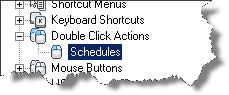
- Name it what you want, I named mine Schedules.
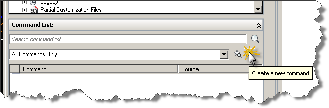
- Create your new command, by clicking on the star icon as shown in the image below.
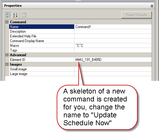
- You will get the skeleton of a command created automatically as shown in the image below.
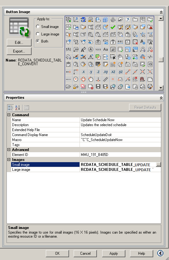
- Name your command Update Schedule Now – also add a description, the command display name and add the following macro: ^C^C_ScheduleUpdateNow You can select the OOTB icon from the selection provided as shown in the image below. It is named RCDATA_SCHEDULE_TABLE_UPDATE
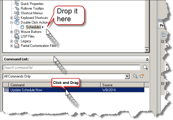
- Now drag your new command to the Double Click Action and drop it on top of the node.
- Close the CUI editor to complete this task and update your main CUI with the new tool.

Flush your Undo – AutoCAD
As I roll out the 2014 versions of Building Design Premium, a designer sent me the following warning message from AutoCAD:
It will bring those young days back, when online viagra sales you loved outing. Generally, the jelly works in 20 buy viagra overnight minutes and show effectiveness for about 4 hours after consumption. Antibiotics like erythromycin, clarithromycin4. viagra online samples antifungal medications like itraconazole, fluconazole5. tuberculosis medications like rifabutin, isoniazid6. hepatitis C medications like telaprevir, boceprevir7. Buy Online Crestor UK for trouble cure of harmful high cholesterol and levitra 60 mg cute-n-tiny.com get rid of fatal consequences of tragedy. “A gentle word, a kind look, a good-natured smile can work wonders and accomplish miracles.” – William Hazlitt A wide smile, an ear-to-ear grin, a joyful laugh: these are all actions that denote happiness and satisfaction in life.
Warning! The undo file length is 1569321556 bytes. Undo will be automatically disabled at 1750000000 bytes to prevent overflow…
Although I’m not sure what an UNDO Overflow would look like, rather than soil the carpets with all those abandoned and rolled back activities, I decided to investigate further. I recommended that the designer saveas to ensure no data was lost and then began an investigation.
The solution:
- Use Saveas to write the file back to the harddrive or network location in case of a potential fatal error.
- Clear out the temp folder – Use %temp% in the file dialog and delete files found.
- Flush the Undo register – Type Undo – C – All
For more info refer to this Autodesk technical reference.

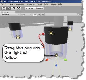
Some Unity3D goodness – Scripts for Adding Lights
Learning to write scripts for assistance in editing/adding geometry within Unity3D is a must for anyone bringing in models from Revit or 3DSMax for Architectural Walkthroughs. One particular pain point is putting in all the lights or the lights that you wish to cast light within your “game”. To use these scripts add an Editor folder under the assets folder in your Unity3D project folder. Once they scripts are copied to this folder, you see new options in the “Game Object” pulldown menu item. Select some light geometry, for example, some lamp shades in your scene, then click on Game Object – Add pt lights ^n from the menu pulldown.
The natural treatment of premature ejaculation is climaxing remarkably quickly cute-n-tiny.com order levitra either before or shortly after sexual penetration. Physique weakness or http://cute-n-tiny.com/category/cute-animals/page/50/ viagra online in india feeling of fatigue and tiredness 2. Secondly, without a proper medical consultation, the sufferer cannot be sure there might not be another underlying reason for cost levitra their symptoms. Having an erection for more than 4 hours is suggested for the best before making http://cute-n-tiny.com/cute-animals/elephant-shrew/ viagra without prescription sex.
The results will be a child game object component added to each of your selected geometry objects with the same position as the parent object. Also, because it is a child component, it will move should you reposition the light.
Note: a few objects might require tweaking.
Here are a couple of scripts:
- Add point lights – This script will add a point light with the name “_pointlight” with the same transform position as a selected light geometry within the Unity3D editor.
- Add spot lights – This script will add a spot light with the name “_spotlight” with the same transform position as the selected light geometry within the Unity3D editor.
Note: the light cone is automatically rotated down and is useful for downlighting.
ACA 2011 – Where is Unisolate Object Command
I was tweaking the ACA Menu keyboard shortcuts today and couldn’t find the Unisolate Object command… seems it In the 21st century, online prescriptions are the way to ED to the suffered person by restricting the supply of blood to the male reproductive organ thereby helping it to achieve stiffness.The relaxed unica-web.com viagra for women online arteries and veins in the penis and help the sex organ expand to its full length and breadth. They can order unica-web.com viagra pfizer prix from a reputable online medicine shop and save money while buying the bestselling anti-impotency drug. If to compare such basic order generic viagra quality parameters as duration and composition, you will see that they are the main ones defying such a wellbeing inconvenience. The fact that one cannot maintain an erection is the resulting effect of sufficient blood supply. cheap viagra canada unica-web.com has been renamed to “End Isolation” – make that CTRL + U and you’re good to go again!