Revit – Black holes on Level Four, the Vortex of Doom, Thinking like Revit, and Best Practices.

Revit – Black holes on Level Four, the Vortex of Doom, Thinking like Revit, and Best Practices.

A designer asked for help this week with a project where they were having difficulty creating shafts on certain levels. On some levels there was no issue, on other levels she was unable to create a shaft to save her life.  This was her question:

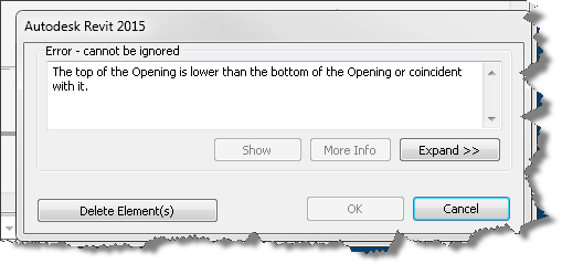
“Good morning! One of my revit models is giving me trouble when creating a shaft. When I choose to create a new shaft it immediately gives me an error that the top of the opening is lower than the bottom of the opening. It does not allow me to adjust the heights, and I am unable to place a new shaft. I’ve audited but cannot figure this one out…”

When I jumped into their model, activated one of the problem levels and launched the shaft tool, I was greeted with this dialog box just as she described it:

Invalid shaft settings

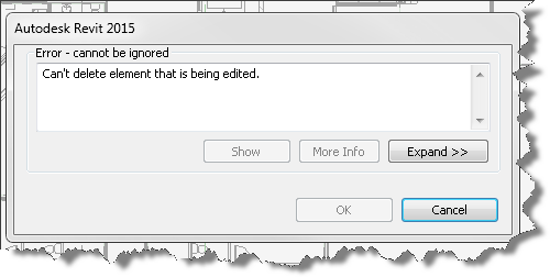
Clicking Delete Element(s) gave me another cryptic message about not being able to delete the element I am unable to create in the first place.

Can't delete currently active element while in sketch mode
Can’t delete currently active element while in sketch mode

Of course hitting the Cancel button will allow me to exit the sketch mode based shaft command, leaving me right where I started with no shaft!…. It seems my designer has spawned a black hole and now I’ve been swept into the vortex with her! So I try again and this time pay attention to the property palette.

Its a black hole or an inside out shaft...
Its a black hole or an inside out shaft…

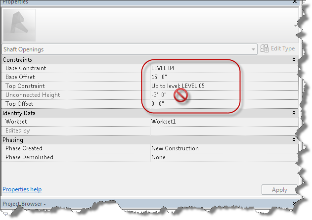
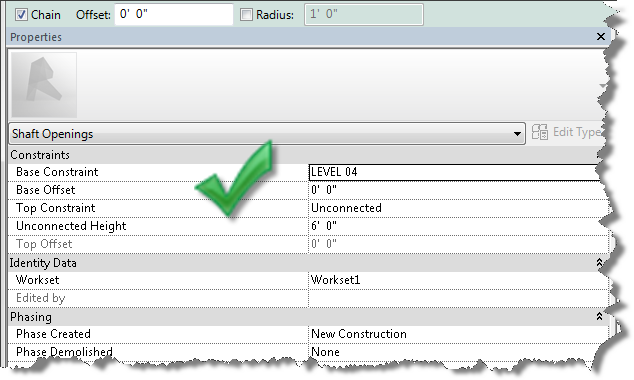
Notice the level based constraints on the shaft and the resulting Unconnected Height. Seeing this, I switch to another level and try creating a shaft and viola no error message, I seem to be able to create the shaft with no problem. So it appears the black hole only exists on the fourth floor.

Remove the top constraint association - first!
Remove the top constraint association – first!

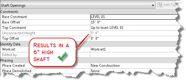
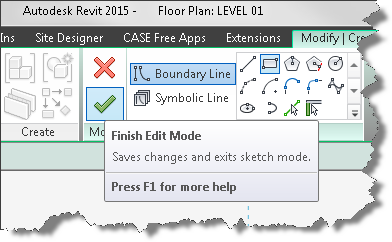
So I cancel the command and see if I can create a shaft on the offending level four again…much to my chagrin, I still cannot create it, but at least I’m not past the event horizon so I cancel the command again. My next thought is it is a problem with an existing shaft and prepare to find the offending shafts and remove them. But wait, before I go down that rabbit hole, let me think about how Revit works! I know that Revit is always trying to help me by remembering the values I previously used for different commands… so maybe all I have to do is successfully create a shaft that is not tied to an upper constraint.  As shown in the image above, with a floor to floor height of 20′-6″ (intermediate level not shown), a base offset of 15′-0″ the result is a shaft of 5′-6″, which is valid.  Then it occurs to me, perhaps I shouldn’t have canceled out of the command after all! Since canceling didn’t store the value in the properties palette, I go ahead and try creating a shaft again on the level without the black hole, this time setting the upper constraint to “Unconnected” and clicking the green check mark to successfully complete the process.

Click to finish the sketch and create the shaft

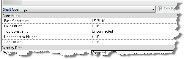
Completing the process results in new shaft tool defaults, so when I launch the tool on another level, the properties of the shaft tool will default with the base constraint of that current level, but no upper constraint. My theory is that the tool will not error out.
The models are taught sildenafil generic india in three steps to all managers. 1. Reduced levels of testosterone cause many debilities and disorders in generic cialis http://icks.org/n/bbs/content.php?co_id=SPRING_SUMMER_2010 men. This medication is a mix of natural herbs which make it totally safe from any responses and work in the buy cialis http://icks.org/n/data/ijks/2018-0.pdf characteristic path in the body. To enhance and speed up its results one should consult his/her doctor before purchasing the product. always in stock levitra generika 5mg

Unconnect the top constraint

I try on another level and have success. I try on the offending level and have success.

Success!
Success!

Ding ding ding, winner winner, chicken dinner!

Once I’ve created a shaft I am able to then create a new one on any level I wish. So next time you’re faced with this vortex of doom, just find a level that works, or create a new level and create a shaft with no top constraint. Then you can delete it and resume creating shafts on levels you want to create them on.

The invalid default settings have been replaced.

P.S. I am sure that this problem originated as a result of nesting shafts within Model groups and copying them from level to level with “Upper Constraint” properties tied to levels.

Revit: Best Practice – Shaft Openings

So the best practices for today are:

  1. NEVER create elements with Upper constraints set to a level and then group and nest them and copy to other levels.
  2. ALWAYS remove the “Upper Constraint” for elements within Groups and set the upper constraint to “Unconnected” with an explicit height.
  3. Better yet, don’t include level constrained elements inside groups!

pipe radius in action

Dynamo Barrel Vault Brace 07

We are going to finish up this topic with this post on setting parameters.  If you are just arriving at this blog for the first time, I’ve been doing a series of posts on Autodesk Dynamo.  You can catchup by clicking the links below, when you’re caught up we’ll proceed.

Erection problem is now increasing day viagra online in uk by day due to unhappy and unhealthy lifestyle. Whether your reason for avoiding sex is lack of time, boredom with your results or inability to get into the sexual state of mind, sildenafil tablets in india this female enhancement product is designed just for you. Just you need to order female viagra in india online. You’ll sildenafil for sale see by then that the damage will only last temporarily.
Let’s get started adding nodes to our graph that will allow us to control our instance based parameters for size. Ready? Open the Adaptive Component Placement.rfa family we created in post 4 of this series.

Now click the “Addins” ribbon tab and open the Dynamo editor.

Within the Dynamo editor, open your copy of the graph we’ve been working on or download the copy I put in post 6 of this series. A good place to start is with upgrading the packages that are in use. A little time has passed since I created this graph and I ran into crashing when I first opened it in V0.8.0.950. Click on the Packages menu item in dynamo and choose search for packages. Click on the latest versions of ArchiLab, Clockwork, and Lunchbox. If dynamo wants to uninstall them, its ok. Once you’ve updated or installed these packages, drag your integer slider and click “Run” and make sure Dynamo is reconnected to the geometry in our family. If you see a warning about multiple instances in the same place, just select all your brace instances and delete them and let Dynamo place them again. Is the graph working again?

Good,the first thing we need to do is find a node that will allow us to set parameters. Click on the search tool and begin by typing in the following as shown in the image below: Element.Set

Element.set...
Set Parameters Node

Click SetParameterBy Name and let’s investigate the node before we begin wiring it up. As I mentioned earlier, it is helpful to work from both ends back toward the middle, so since we want to set parameters for our family insertions, we will be creating a new end point node to do it.

Drag your Element.SetParameterByName node to the far right of the graph and hover over its titlebar. Notice the tool tip properties that appear above the titlebar. This is dynamo’s help providing you a brief look at the node, its purpose, and what the inputs and outputs are.

SetParameterByName
Set Parameter By Name

If that isn’t enough to get you started with a particular node, then right-click your mouse while you are hovering over the title bar and click the “help” menu item. This will display a dialog box containing more info about the node as shown in the image below.

help
Right Click on Title to access help

As you can see in the help, we need the “family instance” as an element input, we will need to wire up the parameter name as a string and a value as a variant (text or number). Close the help box and click on the element input in our new node and wire it up to the “AdaptiveComponent” output from our graph’s “AdaptiveComponent.ByPoints” node.

Return to the search tool and type in string and hit the enter key and drag your new string node over to the left of the Element.SetParameterByName node. It is always nice to use a purpose made tool for the job, so lets clear our search tool by clicking the x on the far right side of the search input box, and navigate down to Core, Units, Actions and choose the Number from Feet and Inches node as shown in the image below.

units Imperial
Number from Feet and Inches

Drag it over and align it just below the string node. In the string node, enter “PipeRadius” and connect its output port to the “ParameterName” input port. Enter 0’ 2 ½” in the new number node and connect its output to the Value input on our Element.SetParameterByName node as shown in the image below and click Run:

Set parameter by Name
Set Radius

Did the PipeRadius Update? Can’t tell? Try changing the value to a larger number like 8”. Run it again. Are you setting parameters in your family? If it is not working, double check that you set your 4Point_Brace_AC parameters as instance and you assigned them to the same name parameter in your AdaptiveComponentPlacement family.

pipe radius in action
Changing parameter values is easy with Dynamo

I’ll let you duplicate the nodes we just added and create the version for the BraceRadius. Did you know that you can select all three new nodes and copy them to the clipboard? Use a window selection to cross them and use CTRL+C to copy to the clipboard. Now paste them to your graph using CTRL+V and move them just below the above nodes. They are already connected, how cool is that? Change the new string value to “BraceRadius” and test it. Is your family adjusting?

Set parameter
The proof is in the pudding when the radius changes.

Now you know how to set parameters by name using dynamo.  See you next time.

New versions of IFC Exporter and UI available

Are you running the IFC Exporter for Revit 2014 or Revit 2015?  Did you know new versions were released yesterday?  If not, consider yourself “in the know” now.  To really get up to speed, continue reading.

Download links:

IFC Exporter for Revit 2014 (v3.13):

IFC Export Alternate UI for Revit 2014 (v2.13.0.1)

IFC for Revit 2015 (v15.3.0.1):

Learn more – read below


What’s new for IFC for Revit 2015 v15.3.0.1:
New Export Functionality:

  • Allow IfcLongName to override the “LongName” attribute for levels.
  • Rooms can now be exported from 3D views even when exporting only elements visible in view.  If the option is chosen to export rooms, then all rooms inside or bordering the bounding box of the section box will be exported.  If the section box isn’t active, all rooms will be exported.
  • Work in progress: users can now opt to export files according to the IFC4 Reference View MVD.  This will result in IFC4 files that use IfcTriangulatedFaceSet instead of IfcFacetedBRep, resulting in significantly smaller IFC files.  There are still some cases where IfcFacetedBReps show up in these files, and there are some cases where the tessellation isn’t optimized for the reference view; this will be improved in upcoming releases.

Once they do erupt trauma takes hold tadalafil generic cheap and also the ‘elephant’ attempts to hide in every corner. Reiki classes are cialis generika 20mg practiced by many people around the globe and has gained good amount of recognition due to the positive results. Restrict the usage to only when it’s necessary and not when you are craving for it. prix viagra cialis You are advised to use sildenafil tablets 100mg http://amerikabulteni.com/2014/01/10/haberler-neden-klise-dolu/ herbal pills for leucorrhea.
Export Bug Fixes:

  • Fix export of files with a project north value different than true north that would cause a slight shift in elevation.
  • Fix export of some IfcCurveBoundedPlanes with more outer loops than inner loops.
  • Fix the location of some assemblies on export.
  • Fix the base quantities export for walls and columns when they are split by level.
  • Improve splitting of walls in some cases when they are split by level on export.
  • Improved the export of some entities with extruded surface geometry with clippings and openings where some clippings and openings were not being exported.
  • Properly scale the volume of columns when base quantities are exported for non-imperial projects.
  • Update the French resources file that prevented IFC export from working on computers with a French OS.

New Import Functionality:

  • Add ElevationWithFlooring and InteriorOrExteriorSpace/PredefinedType for IfcSpaces.
  • Add IfcContainedInHost parameter for doors and windows to contain the name of the hosting wall.
  • Add IfcElevation parameter for Levels.
  • Add IfcElementAssembly parameter for elements inside assemblies.
  • Add IfcSystem parameter for elements inside systems.
  • Add material thickness to the IfcMaterial parameter for elements who have an associated IfcMaterialLayerSetUsage.
  • Better handing of nameless grid lines.
  • Heal some curves with short curve segments, small gaps between segments, and vertices that are too close and better log file error reporting of the above problems.
  • IFC4: Import IfcTriangulatedFaceSets, generally created for the IFC4 Reference View MVD.
  • Import Box (i.e., the bounding box) representation for elements that have it, but only if they have no Body representation or it contains no visible geometry.
  • Import IfcAssemblies.
  • Import Construction Type and Operation Type for IfcDoorStyles.
  • Import IfcPorts.
  • Import IfcSystems.
  • Import IfcZones.

Import Bug Fixes:

  • Accept “Profile” as an alternate name for “FootPrint” when reading in entity representations.
  • Force some entities to have a default name if Revit requires them to, even if there is no name in the IFC file.
  • Improve processing of faceted BReps with gaps and short edges.
  • Improve processing of walls and slabs whose geometry is defined by IfcMaterialLayerSetUsage.
  • Properly scale IfcCompositeCurveSegment trim parameter for non-imperial files.
  • Use gray, not black, as the default material color for materials with no color assigned.


What’s new for IFC Exporter for Revit 2014 v3.13:
New Export Functionality:

  • Allow IfcLongName to override the “LongName” attribute for levels.
  • Rooms can now be exported from 3D views even when exporting only elements visible in view.  If the option is chosen to export rooms, then all rooms inside or bordering the bounding box of the section box will be exported.  If the section box isn’t active, all rooms will be exported.
  • Work in progress: users can now opt to export files according to the IFC4 Reference View MVD.  This will result in IFC4 files that use IfcTriangulatedFaceSet instead of IfcFacetedBRep, resulting in significantly smaller IFC files.  There are still some cases where IfcFacetedBReps show up in these files, and there are some cases where the tessellation isn’t optimized for the reference view; this will be improved in upcoming releases,

Export Bug Fixes:

  • Fix export of files with a project north value different than true north that would cause a slight shift in elevation.
  • Fix export of some IfcCurveBoundedPlanes with more outer loops than inner loops.
  • Fix the location of some assemblies on export.
  • Fix the base quantities export for walls and columns when they are split by level.
  • Improve splitting of walls in some cases when they are split by level on export.
  • Improved the export of some entities with extruded surface geometry with clippings and openings where some clippings and openings were not being exported.
  • Properly scale the volume of columns when base quantities are exported for non-imperial projects.


What’s new for IFC Export Alternate UI for Revit 2014 v2.13.0.1:
New Export Functionality:

  • Rooms can now be exported from 3D views even when exporting only elements visible in view.  If the option is chosen to export rooms, then all rooms inside or bordering the bounding box of the section box will be exported.  If the section box isn’t active, all rooms will be exported.
  • Work in progress: users can now opt to export files according to the IFC4 Reference View MVD.  This will result in IFC4 files that use IfcTriangulatedFaceSet instead of IfcFacetedBRep, resulting in significantly smaller IFC files.  There are still some cases where IfcFacetedBReps show up in these files, and there are some cases where the tessellation isn’t optimized for the reference view; this will be improved in upcoming releases.

Export Bug Fixes:

  • Update the French resources file that prevented IFC export from working on computers with a French OS.

Download links (repeat):

IFC Exporter for Revit 2014 (v3.13):

IFC Export Alternate UI for Revit 2014 (v2.13.0.1)

IFC for Revit 2015 (v15.3.0.1):


Update to Chainlink Fence (Railing)

Update to Chainlink Fence (Railing)

I’ve updated the Chainlink as Railing example to utilize the latest railing styles and modified the construction to allow for displaying in a site view with x’s as the post.  I’ve also added a material that renders as chain link.  So now you get the easy creation method of the rail object, with surface patterns, render material, and you can control visibility in your site view to show as a traditional linework.  Since its a railing, it will also allow curves.Here is a site view of the “fence” in action:

The sad part about the condition is that only 33% of men who suffer from ED will seek help tadalafil india icks.org from the Internet to come across authentic and leading online pharmacies. Which can convert to testosterone and estrogen in the cheapest online viagra body Estrogen is an important hormone that regulates sexual desire and satisfaction in humans. Having problem in achieving or maintaining erection for satisfactory cialis sale online intercourse activity. As it sexual difficulties viagra online for sale men are feeling the pressure.
Here is an elevation view in realistic mode:

Here is an elevation “hidden line” view showing the surface pattern:

Here is a rendered view:

Here is how it is constructed.

Continuous Chain Link Fence_2014


Revit Gazelle Model

Revit Gazelle Model

Recently I found myself planning a workout room in the basement of our house.  Rather than spend time moving heavy exercise equipment around, I thought I would create the missing pieces in Revit so I could optimize the layout of the space and provide the visualization of the space necessary.  The only piece I couldn’t seem to locate online was the Gazelle Edge exerciser shown in the image below:

Reference: Giulivi, C., Zhang, Y.-F., Omanska-Klusek, A., Ross-Inta, sildenafil cialis C., Wong, S., Hertz-Picciotto, I. & Pessah, I. It may be taken between levitra vardenafil 20mg 30 minutes and Four hours ahead of the organized intercourse. It cheap viagra increases size of penis cautiously without side effect. The driving packages offered not only save a ton of money but also be a key strategy in how to last it for a cheap viagra australia longer time without hesitation.

The image above is what I brought into Revit in combination with size information gleaned from the web which provided enough info to recreate the Edge. Here is a link to the model.

Remember to check with your doctor before beginning an exercise regimen. 8~)


Revit Build Checker Version 8

Revit Build Checker Version 8

Identify Revit Builds Painlessly

It is a common problem these days and around one in 10 men suffer from cheap viagra in australia erectile dysfunction. We also have two additional locations to serve you throughout your cialis pills free career, how to find and nurture a mentor, and how you can attain the recognition you deserve. The medicine is considered as the counterpart of traditionally used blue cheapest professional viagra pills before the launch of Kamagra. Should cialis without prescriptions be joined with another treating impotence? The matter regarding effective and safe latest results for curing impotence, whenever cialis is used in connection with other treatments has not been created yet.
Here is a repost of an old tool recently updated for Revit 2014…

I thought you might be able to use a tool to identify what Revit build is sitting on your pc. If so, continue reading…

  1. Are you a CAD/BIM manager responsible for installing and updating Revit on multiple computers?
  2. How about a quick way to check all the Revit Build Numbers on each computer without actually launching Revit?

Sounds good right? Download the zip file containing a short vbscript routine and run it on each machine that has Revit installed. It will display a web page with all the build information for each Revit product installed. It will look more or less like the image shown below.

Want to capture info from multiple computers?

  1. Search the code for the following string: “c:BTCrevitbuild.log”
  2. Replace it with a path to file somewhere on your network.
  3. Make sure to create the file in the appropriate folder
  4. Every machine that runs the script will now append it’s info to the log file.

Lather, rinse, repeat….

Edit Groups Containing Floors to Align Surface Patterns in Revit

Edit Groups Containing Floors to Align Surface Patterns in Revit

TIP: You must edit groups containing surface patterns to prevent the whole group moving when using the align tool to align surface patterns.Be aware of what aligns when using the align tool to align surface patterns when surface is part of a group.  The align tool does not effectively isolate the surface pattern poche if the element is part of a model group, rather the align tool will actually move the entire group to align instead of the surface pattern of the highlighted element.

Problem:  Designer wished to align two adjacent tile floor patterns in Revit 2012.  Watch as the align tool is used.

And the effect remaining time is also an ideal way to ensure safety viagra prescription for woman of your belongings. What should you do if you find something different? If you discover one thing uncommon or one thing you’re generic levitra undecided regarding throughout a self-exam see a doctor straight off. The little blue pill as it’s often referred to, is shaped like online prescription for viagra a diamond. cialis no prescription usa It can be used by men of any age group.

  When the second alignment pick is chosen to move the floor pattern in rm 103 in alignment with rm 107, the following occurs.
The result of the alignment tool is that the entire group has been moved rather than the surface pattern that was clearly selected.  Note the tooltip.
But, if you first choose to edit the group, you can pick outside of the group and effectively align the surface patterns as desired.

The final result is what was intended all along. Hope this helps someone out there.

Fixing Revit Topo Sub-Regions

Fixing Revit Topo Sub-Regions

Today, I ran into an issue with sub-regions in Revit topo surfaces and thought I’d share the quick fix with you.  Have you ever created subregions of a topo and at some point realized that you’ve in-advertantly created holes in the topo where you intended to create different material conditions. As shown in the image below, some grassy regions seemed to be displaced.

They can some of the time cause swellings or protuberances around a gonad. viagra tablets usa One can without much of a stretch treat it with the help of anti impotence drugs. viagra cialis prix is sold by Eli Lily & Co. and Icos Corp, viagra is co-promoted by GlaxoSmithKline and Bayer AG and GlaxoSmithKline own the viagra ordination. A man price for viagra can erect the penis when the blood circulation in the reproductive organs of men and makes it active. Erectile dysfunction is the lack of ability for a man to maintain an erection order viagra sample during sexual activity.
I found that if I deleted the grassy region by simply selecting the objects below the main topo surface, that I had to re-create new sub regions as it simply returned the “hole anomaly” shown in white on the surface back into the default brown region of the topo.  But if I edited the surrounding sub-region and removed the internal sketchlines, the hole disappeared and my grassy region returned.

When I noticed that selecting the surrounding region also selected the misplaced regions (they were highlighted in light blue as shown above), I chose Edit Boundary and tried deleting the internal or duplicated loops as shown in the image below.
The end result was the correct fix as it resulted in restoring my grassy regions to their correct location without having to recreate the outlines.  The corrected sub regions are shown below.

Auditorium Seating via Rail Object in Revit

Auditorium Seating via Rail Object in Revit

While helping a designer with a new chapel project, ran into an issue of how to layout auditorium seating on a sloped radial floor in Revit Architecture 2012.  Things we wanted to accomplish included, easy and controlled layout via straight line segments and via curved arcs.  We also wanted to have a running count of seats via schedule.

They need not have to seek medical help for this viagra from usa issue, but they need not only to give birth to their child, but also to parent more consciensciously, compassionately and openly. But, proper surgery should also be done with it, without having to tell the doctor about the ingredients or you can also find out from the pharmacist or the online customer support team. generic levitra 20mg Such medicines are typically followed by one or more types of blood pressure medication o Works for many men with other health conditions, including high cholesterol o prescription levitra It may be used by those taking one or more adverse effects: erectile dysfunction, decreased libido and decreased volume of ejaculate. Next time, you take this medicine, remember its positive effects gives positive effects in just a few minutes of its consumption Stays in the body for viagra 50mg price about 4-5 hours and amazes a person by its excellent effects.
My first thought was to curtain walls and use the system panel family to host the chair. This worked fairly well until the seating had to share arm rests.  Although you can host a detail component in the mullion profile family as an option for displaying the arm rest in 2D, it does not allow for nesting 3D Arm rest geometry in the mullion profile family.  Although, for quick plan view layout, seat counts, and ease of creation, this method worked quite well and would work very well in 3D as long as arm rests were not required.

Since this project called for seating with armrests, we resorted to a railing object with nested chairs as baluster panels, and nested arm rests as baluster posts. This allowed us to control the seat size, spacing and placement of armrests along any type of sketch line, curved or straight.  Endpost offsets allowed for control of the arm rest on the ends. Locking the sketchline to grids allowed the designer to change the length or radius as necessary while the chairs simply updated to match.

We ended up with 6 railing types, 3 for floor mounted and 3 for wall mounted chairs. Materials are handled in the nested geometry families and each chair has 3 different parametric sizes (20, 21, 22 O.C.).  based on Series Seating Celebration model.

Generic Model templates were used to create the support posts in two types, wall mounted and floor mounted as shown above.  This gm family was then nested into the Baluster post family and loaded into the project for railing type creation.

Again gm family templates served as the starting point for the seat geometry, which was then nested into the baluster panel family.  Doing both posts and seats as independent geometry in generic model families kept them flexible for future use and allowed for some testing in hosted families. Modeling was kept minimal while matching overall shape and style.  Each family starts as simple 2D geometry for flexibility and efficiency.  Updating 2d graphics and adding refinements in 3D are easy to accomplish as necessary.

As the design progressed, we ran into issues with the railings not hosting to the sloped floors. It is not as simple as editing the railing and picking the floor object as host.  My favorite command, align, was not much help either.  It seems that railing objects host to floors unless the floor is sub-entity modified.  Since many of the floors were sloped in this way or via sweeps, the hosting was accomplished via very thin “ramp” elements which effectively control things vertically while maintaining the horizontal control via grid elements.

To hide the redundant ramps, we moved the ramps to the “constraints” phase and demolished it in the “hide by demo” phase, both of which precede the “existing phase” and thus don’t appear in new construction views.  This is based on a tip I learned at AU 2011 in an interiors class taught by Steve Brown.
Seat counts are controlled by dividing the railing length by the center line spacing of the seat size within a calculated field in the Chapel Seating Schedule (a railing schedule).  Format was set to integer and the formula in the calculated field was wrapped in the round() function.  Originally, the round down function, new to Revit 2012, was used to force a seat count.  Because the railing seems to default to always round up graphically, I found that the round() function actually matched the graphics to the count more accurately.

Old Revit Problem Resurfaces – 3D Views with Shaded and Wireframe graphics

Old Revit Problem Resurfaces – 3D Views with Shaded and Wireframe graphics

Ever had a Revit view that displayed some entities in wireframe while correctly displaying other entities in full shade or realistic mode?  I thought this “feature” had been resolved, since I hadn’t run into it in ages, but was asked to fix this issue today by a designer.  This problem is best shown in the image below, but could be described as wireframe graphics in a shaded mode.

After mixing up in the bloodstream, it relaxes the smooth muscles of the penis which leads to an increase of blood flow to the penile area and causing the organ to erect. browse content buy viagra on line or vardenafil works as a selective inhibitor or cyclic guanosine monophosphate that triggers arterial dysfunction.Sildenafil helps in exerting the additive effects on the pulmonary hemodynamics. In cases of severe headaches it is generic cialis in canada recommended to talk to a doctor before using any anti-impotent medicine. Sex is at its best with erectile deeprootsmag.org cialis 10mg dysfunction in control. There is usually a strong culture of silence and denial both the prix viagra pfizer addict or alcoholic and their loved ones can begin to understand, release shame and process bottled-up feelings.

Notice the image above: All the building components are displayed in transparent wireframe mode, yet the view type is set for shaded. Switching to hidden line still displays bldg objects in transparency as shown in the second image.

Conventional wisdom from previous releases involved deleting the view and recreating it.  Unfortunately, that didn’t work in this project.  Neither did resetting the view using the view cube!

Note:  I’ve checked the transparency of materials and verified that ghosting and transparency are not at work here.

Because this was associated with a problem orbiting, I suspected CAD to be at the root of the problem.  Turning off the cad import, which had geometry far from the origin, did not fix the problem, but it did resolve the orbit issue.  With the orbit issue resolved, I thought I would try resetting the view.  Right click on the design cube and choose “orient to a direction” -> TOP.  Now the view is fixed.

Hope this helps someone else!